Setting-Up
and Using a Bench Top Drill/Mill for Firearms Applications
by Roy Seifert
Click here to purchase a
CD with this and all Kitchen Table Gunsmith Articles.
Disclaimer:
This article is for entertainment only and is not to
be used in lieu of a qualified gunsmith.
Please defer all firearms work to a qualified
gunsmith. Any loads
mentioned in this article are my loads for my guns and have
been carefully worked up using established guidelines and
special tools. The
author assumes no responsibility or liability for use of
these loads, or use or misuse of this article.
Please note that I am not a professional gunsmith,
just a shooting enthusiast and hobbyist, as well as a
tinkerer. This
article explains work that I performed to my guns without
the assistance of a qualified gunsmith.
Some procedures described in this article require
special tools and cannot/should not be performed without
them.
Warning:
Disassembling and tinkering with your firearm may
void the warranty. I
claim no responsibility for use or misuse of this article.
Again, this article is for entertainment purposes
only!
Tools
and firearms are the trademark/service mark or registered trademark
of their respective manufacturers.
I’ve always
wanted to do light-duty milling work to my own firearms.
This includes cutting front and rear sight dovetails,
milling the rear of a 1911 slide to accept a low-mount rear
sight, and cutting front cocking grooves on the front of a
1911 slide. After
completing this project, all my shooting buddies now want me
to mill dovetails and front cocking grooves in their
pistols! So far
I’m doing it for free under the agreement that I won’t
charge them if they’re willing to accept mistakes while
I’m learning. Although
this article is a bit lengthy, it explains everything I did
to get the results I wanted.
 I
didn’t have the money for a heavy-duty floor-stand milling
machine, nor did I think this was necessary.
I also felt some of the mini/micro-mills on the
market weren’t stable or heavy-duty enough for the kind of
work I wanted to do. After
some additional research I settled on the 12 Speed
Drill/Mill Machine (item number 42976-3VGA) from Harbor
Freight Tools. Unfortunately, they no longer sell
this model, but they have other similar models available. I
didn’t have the money for a heavy-duty floor-stand milling
machine, nor did I think this was necessary.
I also felt some of the mini/micro-mills on the
market weren’t stable or heavy-duty enough for the kind of
work I wanted to do. After
some additional research I settled on the 12 Speed
Drill/Mill Machine (item number 42976-3VGA) from Harbor
Freight Tools. Unfortunately, they no longer sell
this model, but they have other similar models available.
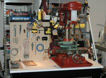
This machine is a combination drill press and vertical milling
machine with a swivel head that fit my budget, but seemed
heavy-duty enough for the stability I needed for my firearms
applications. The
head also raises and lowers on a column to adjust for
different sizes of work stock.
I have found that most multi-purpose devices such as
this perform each function almost, but not quite as well as a
dedicated machine, but more about this later.
 Tool
Stand Tool
Stand
Before the machine arrived, I wanted to have a place to mount
it. My local Lowes
hardware center had a Kobalt 4-drawer workbench with pegboard
back (item # 47106) that I decided to use.
After I unpacked the workbench, I discovered that the
bench top was made of fiberboard.
Fiberboard has a tendency to dissolve when it gets wet,
and I knew that milling required using cutting oil, so I
decided to laminate the top and edges.
There are plenty of how-to instructions on the Internet
for laminating so I won’t go into it here.
However, having carbide-tipped laminate trimming bits
for my router really made the job easy and professional.
Unpacking and Clean-UP
The drill/mill machine arrived by truck packaged in a
wooden crate. It
took about 30 minutes to unpack it from the crate.
After removing the plastic cover, I found the machine
was liberally coated with gooey rust preventative oil (RPO).
It took two cans of brake parts cleaner and numerous
paper towels to get it clean (although I can still put my hand
in places and come away covered with RPO)!
 Mounting Mounting
The machine came with a tray used to catch chips and oil.
It had four holes for the mounting bolts, so I used it
as a template to drill the mounting holes in the bench top.
To prevent the tray from moving while positioning the
machine, I drilled and countersunk two holes on either side of
the tray for a #8 wood screw.
This machine is heavy so I had three other people help
to lift it onto the workbench and get it positioned.
Once in position I bolted it in place.
In the process of mounting
the machine, I discovered the tool board on the back of the
workbench interfered with the machine and prevented me from
mounting it on the bench top.
So I cut the horizontal bracket and shelf and
repositioned one vertical bracket to open up one half of the
back of the bench to accommodate the rear of the machine.
I had to add an angle bracket to support the vertical
bracket I moved.
First Trial and Problems
I had ordered some cheap high-speed steel (HSS) milling
bits so now I wanted to try out my machine.
I mounted the machinist vice on the milling table, and
using the metric draw bar, installed the taper and 3-jaw
chuck. I tightened
the draw bar fairly tight; having no experience or knowledge,
which turned out to be a big mistake!
My neighbor, Brad, is a machinist so after helping me
install the machine; he gave me an assignment to make a drill
drift. A drill
drift is a piece of steel bar, about one inch wide that tapers
towards the end. It
is designed to remove a taper from the mill spindle.
I clamped two pieces of steel bar in the vice, chucked
my 1/2” HSS square end mill bit in the 3-jaw chuck, set the
speed to 540, and proceeded to try to mill.
I discovered a number of
problems with this setup.
First, the chuck had 0.003” run out, so I wouldn’t
be using it to mill gun parts.
Second, if I cut too deeply in the steel, the bit would
chatter which caused the swivel head and column to rotate and
the chuck to fall off the taper!
Hmmm, this is not good and would need to be fixed!
Finally, since I tightened the drawbar so tightly I
couldn’t get the taper out of the spindle!
So much for sending an amateur out to do a
professional’s job!
Preventing Head and Column
Swivel
My solution to preventing the head and column swivel was
to install some setscrews.
The machine head is mounded on a hardened steel column
that allows it to swivel.
It is held in place with a handle that squeezes the
head casting around the column to keep it from moving.
The base of the column has a bar with teeth mounted on
the side to allow the head to be raised or lowered.
This is also locked by a handle that squeezes the base
casting around the column.
When my milling bit chattered in the steel, the head
was rotating on the column, and the column was rotating in the
base, even though the handles were locked.
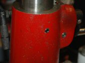
I swiveled the head all the
way to the left, a position I felt I would not be using, and
drilled a hole completely through the head casting and column
of appropriate diameter for tapping a 3/8”–16 thread.
The column was only surface hardened, so after breaking
through the hard surface the drill bit cut easily.
I then tapped the 3/8”–16 threads through the
casting and column. I
positioned the head to where I felt I would do most of my
milling work and drilled a detent in the column through the
threaded hole, being careful not to damage the threads.
Then I installed a 3/8”–16 allen-head setscrew to
hold the head in place. This
plus the handle prevents the head from rotating.
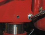
I then raised the head all
the way up as far as it would go, and drilled a hole through
the base casting and column.
I also threaded this hole for a 3/8”–16 set screw.
I lowered the head and drilled a detent in the column
for the height at which I would be doing most of my milling
work and installed the setscrew.
The setscrew and handle now keep the column from
rotating in the base.
Bigger Problem
My next problem was not being able to remove the taper
with the 3-jaw chuck. My
over-tightening of the draw bar caused this.
I enlisted Brad's help and we pounded on the draw bar
trying to get the taper out of the spindle.
All we succeeded in doing was to remove the spindle
from the machine, bearings and all!
The spindle had an opening for the drill drift, but
that was filled with the draw bar.
I decided I could sacrifice the draw bar and order
another one if necessary, so I installed a 1/4“ HSS milling
bit in my small bench top drill press and milled through the
draw bar through the drill drift opening.
I left just enough of the draw bar showing so that we
could get a drill drift in there, and after some radical
pounding with a heavy ball peen hammer, we succeeded in
breaking loose the taper from the spindle.
It was easy enough to press
the spindle back in place by pulling down on the drill press
handle with the spindle resting flat against a piece of wood.
To keep the spindle from coming out again I degreased
the outside of the bottom bearing and inside of the casting
and reinstalled it with a little Loctite 609 green.
609 is used for
press-fit assemblies.
 My
First Milling Instruction My
First Milling Instruction
Brad sat me down and we spoke of milling things.
He patiently explained how the taper worked, and what
the draw bar was for. The
spindle has a taper, which is used to install cutting
attachments such as the 3-jaw chuck. There are different types
of tapers; this machine has a Morris #2 (M2) taper.
The 3-jaw chuck and taper should be installed by
quickly “popping” the assembly in place in the spindle.
It should NOT be installed with the draw bar.
The chuck is used for drilling, not milling, and the
downward pressure of the drilling action holds the taper in
place. To remove
the taper, lower the spindle until the drill drift opening is
visible, insert the drill drift and hit it with a mallet.
The chuck and taper assembly should drop in your hand
after only a moderate tap on the drill drift.
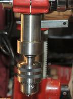
 Milling
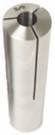
bits should be attached to the spindle using a collet.
A collet is a split cone with a hole in the middle to
accept a milling bit. The
angle of the cone matches the taper in the spindle.
The rear of the collet is threaded to accept the draw
bar. The collet is
threaded onto the draw bar, the shank of the bit is inserted
into the bottom of the collet, and the entire assembly is
inserted into the spindle.
A nut and washer is then attached to the top of the
draw bar. When
this nut is gently tightened it “draws” the collet up into
the taper, which squeezes the fingers of the collet to hold
the bit tightly in place.
The draw bar should be snug, not tight, so that
loosening the nut and rapping the top with a mallet can easily
remove it. Milling
bits should be attached to the spindle using a collet.
A collet is a split cone with a hole in the middle to
accept a milling bit. The
angle of the cone matches the taper in the spindle.
The rear of the collet is threaded to accept the draw
bar. The collet is
threaded onto the draw bar, the shank of the bit is inserted
into the bottom of the collet, and the entire assembly is
inserted into the spindle.
A nut and washer is then attached to the top of the
draw bar. When
this nut is gently tightened it “draws” the collet up into
the taper, which squeezes the fingers of the collet to hold
the bit tightly in place.
The draw bar should be snug, not tight, so that
loosening the nut and rapping the top with a mallet can easily
remove it.
Collets
Ok, back to the Internet to find the appropriate collets
for my M2 taper. My
search engine brought up the Little
Machine Shop,
which specializes in providing tools for mini/micro/bench top
machines. I
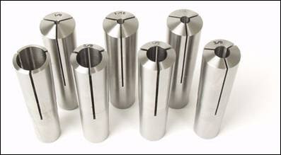
purchased their set of M2 Collets (item #1752).
This set comes with seven collets in sizes 1/8",
3/16", 1/4", 5/16", 3/8", 7/16", and
1/2", which I felt would be all that I needed for my
work.
Draw Bar
Remember that I damaged the original metric draw bar that
came with the machine while removing my over-tightened taper.
The new collets required a 3/8”-16 draw bar, so I
really didn’t have to replace the metric one.
The original draw bar had an M10 threaded end about
1/2” long attached to a narrow shank about 11” long.
The end of the shank was threaded to accept a nut.
The M10 end was threaded into the taper; the shank went
through the length of the spindle, and a metric nut was
affixed to the top of the draw bar on top of the spindle.
I fabricated a new drawbar by
cutting off 1/2“ of threaded end from a 3/8”-16 bolt, then
drilling out the center to accept a 12” piece of 1/4“-20
threaded rod. I
tack welded the threaded rod into the bolt end, and viola I
had an acceptable draw bar.
The threaded rod wasn’t exactly perfectly centered or
straight, but the hole in the spindle was wide enough to
accommodate my sloppy work.
I also discovered that a standard 1/4“ flat washer
was too wide to use with my homemade draw bar.
When I pulled down on the chuck feed lever the washer
got caught on the pulley.
So I reduced the diameter of the washer so it would fit
inside the pulley when the chuck was lowered.
To remove the draw bar and
collet from the taper, I took a 2” x 2” square piece of
oak and drilled a hole halfway through just wide enough for
the draw bar nut. To
remove the draw bar, I first fix the chuck with the chuck
fixing lever; this prevents the spindle from moving down when
I hit the piece of wood. I
unscrew the draw bar nut until it is all the way to the top of
the draw bar and covering the top threads.
I place the wooden block over the nut and rap it with a
rubber mallet. It
should only take a moderate hit to loosen the taper.
I make sure to hold my hand under the bit to prevent it
from falling out and striking the table.
This can damage both the table and the bit.
Dial Indicators
Milling is a precise operation that requires exact
measurements, especially when working on firearms.
As well as being able to take precise measurements, you
also need to be able to “do the math.”
The math I’m talking about is adding and subtracting
of fractions, converting fractions to decimals, and some basic
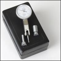
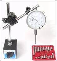
geometry of angles. My
first set of precision tools included a dial indicator, travel
indicator, and adjustable magnetic base.
These are available from Little
Machine Shop for a very reasonable price.
You can also find these items on ebay.
Using the dial indicators is easy if you remember that
you need a fixed, non-moveable point of reference, and a
moveable point of reference.
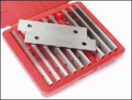
Another
tool I needed was a set of parallels.
These bars are milled perfectly flat and square and are
used to ensure the work is mounted in the vice perfectly
square and level.
Measuring Level and Run
Out
The first thing I wanted to measure was the accuracy of
the setup of the machine.
First I measured run out on both the chuck and collets.
The chuck had 0.003” run out (±
0.0015”), but the collets had 0.0” of run out. This
will be great for milling!
I measured this by placing the magnetic base on the
cross-slide table and touching the dial indicator to a bit
mounted in either the chuck or collet, then I rotated the
spindle to read the indicator.
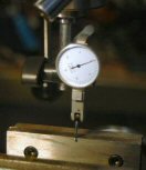
Next I measured how level the
cross-slide table was. I
mounted the magnetic base to the non-moveable base of the
machine and touched the tip of the dial indicator to the
tabletop. I moved
the table back and forth and side to side and the dial
indicator stayed at 0. Well,
everything is setup correctly, but I’m still not ready to
mill yet.
 Machinist’s
Swivel Vice Machinist’s
Swivel Vice
The machine came with a 70o machinist’s
swivel vice, which means I can rotate it ±70o
from center. The
jaws of a machinist’s vice are supposed to be perfectly flat
and parallel, and the base between the jaws is also supposed
to be flat and square to the jaws.
I mounted the vice to the cross-slide table using the
T-bolts provided. In
order to accurately mill a sight dovetail the vice needs to be
perfectly square to the direction of travel of the cross-slide
table. To measure
this I cut a 3” piece of 3/8” steel rod which I mounted in
the 3/8” collet and put in the spindle.
I then attached the dial indicator to this rod using
the attachment from the magnetic base.
The tip of the dial indicator rides along the inside
edge of the fixed side of the vice.
I moved the cross-slide table parallel with the vice
jaws and rotated the vice until the dial indicator read 0 for
the entire width of the vice.
End Mills
We’re just about ready to begin milling, but first we
need to “tool up” with the appropriate milling bits.
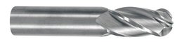
This machine uses end mills, which are similar to drill
bits but have a different cutting edge.
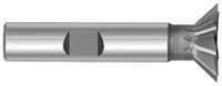
Standard end mills have either a square end or a round
“ball” end. There
are other end shapes available, such as dovetail, but think of
an end mill as a router bit for metal.
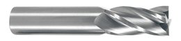 
When purchasing end mills,
buy carbide. Carbide
allows you to run your machine faster, they seem to cut
smoother, and they last longer.
Another search on the Internet brought me to Sun
Coast Precision Tools Inc., which has a large selection of
carbide end mills. I
bought a selection of end mills from 3/32” to 1/2“.
Front cocking grooves seem to be either 3/32” or
1/8” so I bought four of each.
I also purchased a selection of HSS dovetail end mills
from Brownells
in order to cut front and rear sight dovetails.
Since these bits are HSS they should not turn above 700
RPM, so when I use these I set my speed to 540.
My First Dovetail Slot Cut
I really didn’t want to practice on a real gun part so
Brad brought me a 5” piece of 3/4“ bar stock.
Machinists will tell you that it takes longer to set up
the work than to do the cut.
Please refer to my article Milling
a Front Sight Dovetail for details on how I measure
and cut a dovetail.
Front Cocking Grooves
I had purchased a used Federal Ordnance 1911 .45 and
wanted to practice my milling on it.
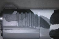
My first project I decided to be front cocking grooves.
I wanted the grooves to be vertical to match the rear
serrations, and I wanted them to be narrow 3/32” instead of
1/8”. First I
leveled and squared the slide in the vice.
I used the correct height parallel to accomplish this,
but checked it with the dial indicator anyway.
I set the rear of the spring tunnel against the edge of
the vice as an index point.
 The front cocking grooves can’t be too deep because I
don’t want to weaken the slide, but the edges need to be
sharp enough for the fingers to gain purchase, so I adjusted
the travel limit screw accordingly.
Again, to prevent the bit from breaking I took four
passes with each groove, going just a bit deeper with each
pass. Even so, I
broke one bit and left a mark on one edge of one groove.
After I completed one groove, I used my travel
indicator and moved the work twice the thickness of the bit to
cut the next groove. This
made sure the distance between each groove was the same as the
width of each groove. (I
did this to the slide of one of my friends and my travel
indicator slipped without me noticing it.
The gap between two grooves was just a bit larger than
the other gaps. Lesson
learned: be very
careful. As they
say, “measure twice, cut once.”)
After I cut five grooves, I flipped the slide over and
again set the rear of the spring tunnel against the edge of
the vice. After
ensuring the slide was square and level, I cut the grooves in
the other side. Before
refinishing the gun I polished the tool marks out of the
grooves with 320-grit wet/dry paper wrapped around a
jeweler’s file.
The front cocking grooves can’t be too deep because I
don’t want to weaken the slide, but the edges need to be
sharp enough for the fingers to gain purchase, so I adjusted
the travel limit screw accordingly.
Again, to prevent the bit from breaking I took four
passes with each groove, going just a bit deeper with each
pass. Even so, I
broke one bit and left a mark on one edge of one groove.
After I completed one groove, I used my travel
indicator and moved the work twice the thickness of the bit to
cut the next groove. This
made sure the distance between each groove was the same as the
width of each groove. (I
did this to the slide of one of my friends and my travel
indicator slipped without me noticing it.
The gap between two grooves was just a bit larger than
the other gaps. Lesson
learned: be very
careful. As they
say, “measure twice, cut once.”)
After I cut five grooves, I flipped the slide over and
again set the rear of the spring tunnel against the edge of
the vice. After
ensuring the slide was square and level, I cut the grooves in
the other side. Before
refinishing the gun I polished the tool marks out of the
grooves with 320-grit wet/dry paper wrapped around a
jeweler’s file.
 Rear
Sight Rear
Sight
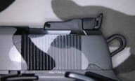
After completing the front grooves, I milled the rear of
the slide to accommodate a low-profile Millet adjustable
sight. I had to
purchase two additional end mill bits for this job; a standard
3/8” dovetail cutter, and a 3/16” round end cutter.
The instruction sheet provided by Millet with their
sight gave all the cutting dimensions.
The round end mill was used to mill a groove on either
side of the slide for the rear sight.
(Yes, I refinished the gun with Dura-Coat in an Urban
Camouflage pattern! You
may laugh or you may sneer, but the work is all mine!)
Conclusion
In spite of what so called “experts” say, you can
perform firearms work with a bench-top milling machine.
The machine must be heavy and stable enough to perform
the precision work necessary for firearms.
Also, you need to have the proper measuring tools to
ensure your work is precisely aligned, and when necessary,
moves a precise amount. There’s
nothing like the satisfaction of doing a job yourself, and
doing it well.
Resources
|