Building
a Backpacker “Scout” Rifle
by Roy Seifert
Click here to purchase a
CD with this and all Kitchen Table Gunsmith Articles.
Disclaimer:
This article is for entertainment only and is not to
be used in lieu of a qualified gunsmith.
Please defer all firearms work to a qualified
gunsmith. Any loads
mentioned in this article are my loads for my guns and have
been carefully worked up using established guidelines and
special tools. The
author assumes no responsibility or liability for use of
these loads, or use or misuse of this article.
Please note that I am not a professional gunsmith,
just a shooting enthusiast and hobbyist, as well as a
tinkerer. This
article explains work that I performed to my guns without
the assistance of a qualified gunsmith.
Some procedures described in this article require
special tools and cannot/should not be performed without
them.
Warning:
Disassembling and tinkering with your firearm may
void the warranty. I
claim no responsibility for use or misuse of this article.
Again, this article is for entertainment purposes
only!
Tools
and firearms are the trademark/service mark or registered trademark
of their respective manufacturers. All tools were
purchased from Brownells
unless otherwise indicated.
Introduction
Col. Jeff Cooper developed the scout rifled concept. His
definition of a scout rifle was a bolt-action with a crisp
3-pound trigger chambered for the .308 Win. cartridge. It
should weigh between about 6.5 and 7.5 pounds, with an
overall length of some 39.5 inches. It would feed from a
detachable-box magazine and have ghost-ring iron sights as
backup or reserve sights. Probably the most unusual feature
of Cooper's design was the forward-mounted, low-powered
scope. Although he said this was not mandatory, it would
preserve the shooter's peripheral vision, keep the ejection
port open to allow the use of stripper clips to reload the
rifle, and eliminate any chance of the scope striking one's
brow during recoil.
To
Cooper, the Scout was to be a general-purpose rifle for
hunting and personal defense. He didn’t care for the .223
Rem. cartridge, nor did he think the Scout Rifle needed more
power than the .308 Win. His idea was a short, compact
rifle that could successfully deal with targets up to about
200 pounds at whatever range the shooter could keep his
shots in an 8-inch circle, i.e. 2 minute-of-angle (MOA)
which is 2-inches at 100 yards, 4-inches at 200 yards, or
8-inches at 400 yards.
Cooper
felt a semi-auto rifle would work if the action were simple
and it met the weight requirement. I’m guessing that he
never considered a lever-action rifle because it didn’t take
a box magazine, and the lever would hit the ground when
cycling in the prone position. The tubular magazine of a
lever gun has a limited capacity, and can’t take spitzer
bullets because of the danger of setting off a round in the
magazine due to recoil. Hornady manufactures their
LEVERevolution® cartridges using their FTX® bullets. This
Flexible Tip eXpanding bullet has a better ballistic
coefficient than a typical .30-30 round nose bullet, which
makes it more accurate, and the soft tip makes it safe to
load in a tubular magazine.
However,
the lever-action is faster than a bolt action, and although
limited in capacity, the magazine can easily be topped up.
Some of the newer lever-action rifles manufactured by
Henry can only be loaded from the front of the magazine
tube like a .22 which makes them more difficult, but not
impossible to top up.
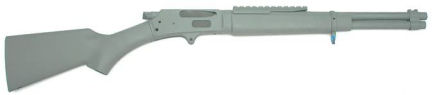
Marlin
336 .30-30
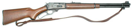
Being a
big fan of lever-action rifles, I decided to build a
backpacker scout rifle. I found a used Marlin 336 on
Gunbroker.com for a mere $300. With shipping and my FFL
dealer’s transfer fee the total came to $348, which I
thought was a great price. I’ve seen these rifles in pawn
shops and in used rifle racks as low as $200.
As soon
as I had the rifle in my shop I took it apart to do an
inspection. The rifle came with quick-detach sling swivels
and a leather “cobra” sling. According to the table at the
end of this article, this rifle was built in 1976 which
makes it a pre-Remington “bicentennial” rifle.
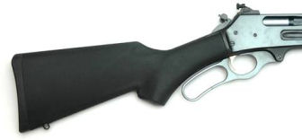
Fit and
finish of this rifle were excellent, except for a sliver of
wood missing from the wrist of the butt stock where it met
with the receiver. Although this was disclosed by the
seller, I plan to replace the butt stock with a synthetic
butt stock. The wood had some dings and scratches from
normal wear, which was to be expected.
The
action was smooth; with the hammer down I could work the
action with one finger. Using my trigger pull gauge, 8.5
pounds of force were required to lever the action. My
extensively reworked 1894CB only requires 3.25 pounds of
force to lever the action. I realize the 336 has a heavier
bolt, but I can certainly get that 8.5 pounds down.
The
trigger had some creep and was rough, but broke at 5.5
pounds. The bore was bright and clean with no signs of wear
or corrosion. The rifle was very dry, probably from sitting
in a gun safe or cabinet, but overall the rifle appeared to
have been well cared for with no signs of rust, but not used
very much. It also appeared to have never been worked on
because all the parts still had bluing except where they
rubbed together during normal use.
To my
surprise, this rifle did not have the cross-bolt safety;
that was not added until 1984. To carry the rifle safely
with a loaded round in the chamber I would have to carefully
place the hammer into the half-cock position like other
shooters have done for over 100 years. Another interesting
quirk about this rifle, the butt stock did not have the
signature bullseye because someone removed it and installed
a sling swivel stud with epoxy and/or plastic wood.
Build
Plan
To build my backpacker scout I plan to perform the
following:
·
Polish
and tune the internals and perform a trigger job
·
Cut the
barrel to 16.5-inches – 16-inches is the minimum legal
length for a rifle barrel
·
Cut the
magazine tube to match the cut barrel
·
Install a
synthetic youth butt stock so it fits my shoulder better
·
Convert
it into a takedown rifle like I did to my Rossi ’92 (refer
to my article
Building a Lever-Action Takedown Rifle).
·
Add a
scout rail to the barrel
·
Apply a
camouflage pattern using spray paint
·
Add a
scout scope or red dot sight to the rail
·
Add
backup ghost sights to the receiver
I found a
Marlin 336Y youth model on Gunbroker.com for $300 dollars,
but I was afraid it was built by Remington and I didn’t want
to spend time attempting to repair a poorly built rifle.
The youth model comes with a 16.5-inch barrel and a shorter
butt stock, but I wanted to do the gunsmithing myself.
Polishing
Tools
A word about polishing – I read many gunsmiths say to just
polish and not remove any metal. Polishing, by its very
nature, removes metal. In most cases, the goal of polishing
is to remove burrs, high spots, and tooling marks, but not
alter the shape of the part. I used the following tools to
perform the polishing work:
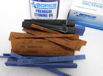
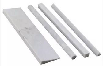
·
400 and
600-grit polishing sticks – available from
Boride Engineered Abrasives. They make a gunsmithing
kit with coarse and fine, wide and narrow polishing sticks
that I have used on many guns. Oil is used to clean these
polishing sticks.
·
Fine
Arkansas stone – available from Brownells. They make a
4-stone set
#975-104-000 that comes in different shapes perfect for
gunsmithing use. Oil is used to clean these stones.
·
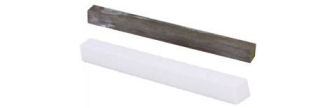
Ceramic
Polishing Stones, Black Medium-Fine
#080-721-604 White Extra Fine
#080-721-601 – Available from Brownells used to polish
the sear. Water is used to clean a ceramic stick.
·
400 and
600 grit wet/dry sandpaper – Available at most hardware
stores. When placed on a flat surface, or wrapped around a
dowel or flat stick I use this to polish large areas.
Working
on the Bolt
To begin
slicking up the action I worked on the bolt first. I ran a
220-grit polishing stick in the ejector groove to remove the
milling marks. I polished again with a 400-grit stick, then
finished polishing the groove with 600-grit wet/dry sand
paper wrapped around a flat stick.
I then
polished the channel in the bolt where the tip of the lever
rides with a 400-grit stick. I polished the inside edges,
and removed the burrs from the outside edges.
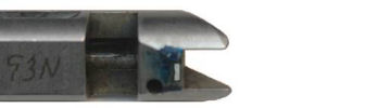
Many
gunsmiths or tinkerers reduce the hammer face so the bolt
doesn’t have to exert so much pressure on the hammer
spring. I use a slightly different method as described in
Accurizing the Factory Rifle by M. L. McPherson. I
used a blue marker to color the underside of the bolt where
it rides on the hammer. I cycled the action a few times so
I could see the wear mark. This highlighted the camming
surface that cocks the hammer when the bolt is levered to
the rear.
I used my
milling machine and milled off most of the camming surface
leaving about 1/8”. This reduced the amount of surface area
riding on the hammer, which reduced the amount of pressure
riding on the bolt.
I used a
Cratex tip and my Dremel tool to polish the cam so it would
ride smoothly over the hammer. This surface was rough from
the factory and needing some smoothing.
Finally,
I used a 400-grit polishing stick to polish off the high
spots from the inside of the locking bolt channel. I was
careful not to change the dimensions of this channel because
I still wanted the locking bolt to fit properly. In the
photo above you can see where I have begun to remove some of
the high spots.
Polishing
the Firing Pin
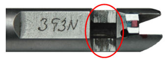
I disassembled the bolt to work on the firing pin. The bolt
comes apart with two roll pins. To get to the front roll
pin I had to remove the extractor by prying it from the
bolt.
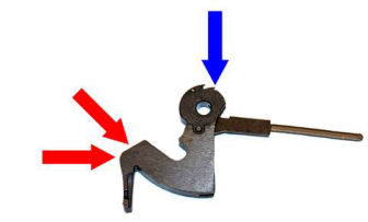
The top
of the lever rubs against the firing pin in two places; the
front cutout as indicated by the worn bluing in the above
photo, and the front edge of the notch as indicated by the
arrow. I polished both areas with a 400-grit polishing
stick.
Sticky
Bolt
After reassembling the bolt, I discovered the bolt was
dragging in the receiver. I found that in the process of
disassembling the bolt I had bent one of the legs of the
extractor so it wouldn’t sit completely down in the
extractor cutout. It was raised just enough to drag on the
inside of the receiver.
I removed
the extractor and bent the two legs closer together. This
applied more pressure on the bolt, which allowed the
extractor to sit completely down into the cutout in the
bolt. The bolt now slides freely in the receiver.
Working
on the Ejector
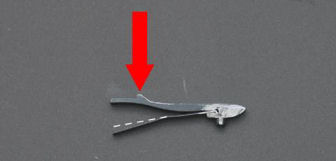
I
polished the sides of the ejector by rubbing them on
600-grit wet/dry sand paper placed on a flat surface. I
used a Cratex tip and my Dremel tool to polish the tip that
rides in the groove in the bolt. After polishing I
cold-blued the ejector with Brownells Oxpho-Blue Creme
#082-124-004.
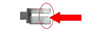
I bent
the ejector spring just a bit as indicated by the dashed
line in the above photo. This was so the ejector wouldn’t
put too much pressure on the bolt. After bending the
spring, the bolt rode more smoothly in the receiver, and the
ejector still ejected cases properly.
Working
on the Trigger Safety Block Spring
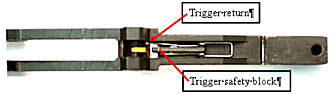
I removed
the trigger guard plate from the bottom of the receiver.
The trigger safety block spring performs two functions; it
activates the trigger safety block (bottom leg in the above
photo), and is the trigger return spring (top leg in the
above photo). This spring is very stiff by design, but can
be lightened. I used a dental pick to carefully bend up
each leg so there wasn’t so much tension on the trigger or
trigger safety block. Both still functioned as designed,
but the trigger pull was much lighter. This was a trial and
error process; each leg of the spring must still provide
tension.
Working
on the Sear
Caution, this work should not be performed without the
proper tools to prevent rounding the sear which could cause
the rifle to become unsafe.
Ok, with
the necessary disclaimer out of the way let’s talk about
trigger pull. There are primarily three things that affect
the weight of trigger pull; trigger return spring tension,
hammer spring tension, and the sear engagement angle with
the hammer. The trigger return spring tension can be
reduced by replacing the spring, bending the spring, or
cutting coils. As mentioned before, I carefully bent the
leg of the trigger safety block spring that acts as the
trigger return spring to reduce spring tension.
The
hammer spring, or mainspring, forces the hammer notch
against the trigger sear. The heavier the spring, the more
pressure is placed on the sear, which requires more pressure
on the trigger to release the sear. A lighter hammer spring
can lighten the trigger pull, but as you will see, I
installed a factory hammer spring. A perfectly smooth, flat
sear with the proper angle can go a long way to reducing the
amount of pressure necessary to release the sear.
I wanted
to polish the sear to get it glass smooth and flat which
would eliminate any gritty feel. I also wanted to change
the angle just a bit to lighten the trigger pull. I
disassembled the trigger guard plate assembly and removed
the sear by drifting out the pin holding the trigger and
sear in place.
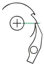
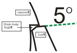
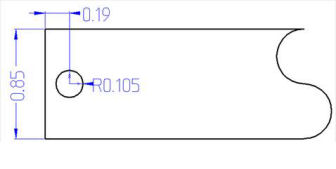
As
mentioned before, the hammer and sear mating surfaces should
be flat and square so the entire surfaces meet. I’ve worked
on some Marlin sears that were ground crooked so only one
edge mated with the hammer. They should also be in line
with the center of the pivot point of the hammer as shown by
the green line in the above diagram.
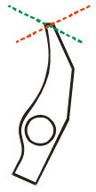
Trigger
pull can be increased or decreased by changing the angle of
the sear. Changing the angle in the direction of the green
line increases trigger pull. Changing the angle in the
direction of the red line decreases trigger pull. This must
be done carefully; if the sear is cut too much in the
direction of the red line the hammer can slip off the sear
and cause an unsafe condition.
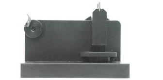
I already
had the Power Custom Series I Stoning Fixture
#743549 and purchased the Marlin 336 Adapter
#917687; both came from MidwayUSA.com. I installed the
adapter onto the fixture, and installed the sear onto the
adapter. I marked the sear surface with a blue marker and
adjusted the guide so my black, medium-fine ceramic stone
was polishing the sear surface flat.
I
adjusted the guide up 20 clicks to change the angle of the
sear by 5-degrees to make the trigger pull lighter. The
adjustment screw is a 7/16-16 screw, which is 16 threads per
inch (TPI). The adjustment wheel has 4-clicks per turn.
One click is about 1/4-degree of change, one full turn of
the wheel is about 1-degree of change, so 20-clicks is 5
full turns, which is about 5-degrees of angle.
I used a
400-grit polishing stick to cut the new sear angle, then
used the black medium-fine ceramic stone to polish the new
sear surface. I finished polishing with the white,
extra-fine ceramic stone until the sear surface looked like
a mirror.
After
changing the sear angle, I reversed the sear in the jig and
ground a break away angle in the rear of the sear. This
causes less of the sear to contact the hammer further
reducing trigger pull.
Working
on the Finger Lever
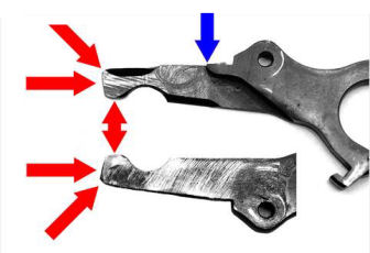
Each side
of the top of the finger lever had rough tooling marks and
worn bluing where it was rubbing on the inside of the bolt
and the carrier. I polished both sides with a wide 400-grit
polishing stick. I didn’t remove all the tooling marks, but
I polished just enough to remove any burrs and high spots.
I rounded the sharp edge shown by the blue arrow in the
above photo which helps to prevent the rifle from jamming.
If left sharp, this edge can cut into the carrier, which can
cause jams.
I used a
Cratex bit to polish the end of the lever as shown by the
red arrows in the above photo. These areas ride against the
inside of the bolt and firing pin.
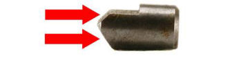
The
finger lever plunger keeps the lever in place when the
action is closed. The two angled surfaces were rough and
had tooling marks. I removed the pin that holds the plunger
in the lever and polished the two angled surfaces with a
400-grit polishing stick until the tooling marks were
completely removed. I reinstalled the plunger with a Wolff
reduced power finger lever plunger spring
#33105. Some folks cut coils off the spring instead of
replacing it, but if the spring is too weak it won’t hold
the lever closed.
Replacing
the Hammer Spring
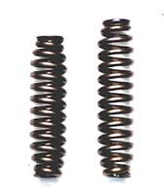
When I
disassembled the rifle, I discovered a previous owner had
replaced the factory spring with a Wolff reduced power
hammer spring
#32501. I read an article on the Internet that stated
reduced power hammer springs can cause erratic ignition,
which can cause accuracy problems. After performing all the
polishing, I replaced the reduced power hammer spring with a
factory spring. The action was much smoother, and I could
easily cycle the action with the rifle on my shoulder.
Working
on the Hammer
The
hammer required a little bit of work to make it smoother,
and to make the trigger pull crisper. I used a Cratex bit
and my Dremel tool to polish the face and top curve of the
hammer as indicated by the red arrows in the photo above.
The full-cock notch (blue arrow) measured 0.030” which made
the trigger pull long with some creep. Using a 400-grit
polishing stick, I reduced the depth of this notch to 0.018”
which made the trigger pull nice and crisp with no creep,
but still safe. I was careful not to reduce the depth of
the notch too much, otherwise the sear could contact the
half-cock notch and break it when the hammer is released.
After working on the sear and hammer, the trigger pull was
crisp with no drag and measured 2-pounds. 6-ounces.
Polishing
the Locking Bolt
I didn’t
do much polishing on the locking bolt since it already slid
smoothly in the receiver. Using a 400-grit polishing stick,
I polished the sides to remove the high spots and burrs, and
polished the front where it impacted the bolt. I used a
Cratex bit to polish the indentation where the rear firing
pin rides.
Polishing
the Carrier
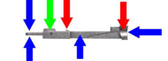
I
polished the front and top of the carrier where the
cartridge cases ride, and the sides where the pivot screw
hole is located with a 400-grit polishing stick (blue
arrows). I polished the concave area where the cartridges
ride into the chamber, and the tip of the carrier rocker
with a Cratex bit (red arrows). Finally, I polished the
sides of the carrier rocker by rubbing them on 600-grit
wet/dry sand paper placed on a flat surface (green arrow).
I cleaned everything off with brake parts cleaner,
lubricated the carrier rocker with grease, and reassembled
the carrier. I applied a small amount of grease on the flat
sides around the pivot screw hole, and in the hole itself
and reassembled the rifle.
Fabricating a Front Barrel-Band
One
problem I immediately noticed with this rifle was that the
magazine tube was pressing against the end of the barrel,
which would probably have a negative effect on accuracy.
Minimizing the amount of contact with the barrel should
provide some increase in accuracy. I believe the reason
Marlin did this was so the 6-40 barrel-band screw would fit
through the notches in the barrel and magazine tube to hold
the magazine tube in place. To accomplish this the front
barrel-band had to squeeze the magazine tube closer to the
barrel, which caused it to touch the barrel. This also put
some tension on the magazine tube.
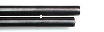
With the
front barrel-band removed you can see that the magazine tube
is straight and not touching the barrel. The gap measured
0.090”. The rear barrel-band screw doesn’t even touch the
magazine tube, which will make it easy to move forward for
disassembly once I convert the rifle into a takedown.
I decided
to fabricate a new front barrel-band for two reasons; one
because I plan to cut the barrel down to 16.5 inches so the
original front-barrel band won’t fit because of the barrel
taper. I could ream the barrel-band, but it will sit back
too far from the end of the muzzle for my purposes. Reason
two, the front sight will be an integral part of the new
barrel-band. I won’t have to drill and tap the barrel for
the factory ramp, therefore, the new barrel-band can set
closer to the muzzle. This allows me to fabricate a shorter
magazine tube plug, which saves some usable capacity in the
magazine tube. The new barrel-band won’t squeeze the
magazine tube close to the barrel; the tube will be
straight, which will eliminate any stress or flex making it
easier to pull forward for disassembly, and it won’t touch
the barrel.
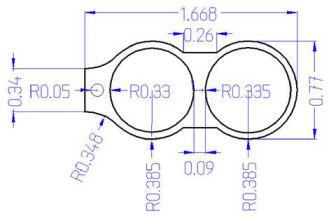
I
carefully measured the diameter of the barrel and the
magazine, and measured the distance between the bottom of
the barrel and top of the magazine tube at the location of
the new barrel-band. I increased the diameter of the
magazine tube hole so the magazine tube wouldn’t bind; it
must be able to move freely. I fabricated the new front
barrel-band out of 3/4” 6061-T6 aluminum. Everything was
the same as the barrel-band I fabricated for my
Rossi ’92 except I milled a contour to the sides instead
of leaving them straight.
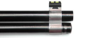
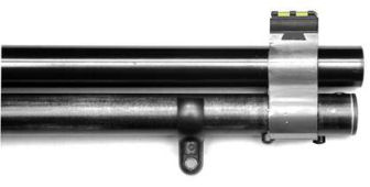
I ordered
a Williams 336 WGRS Fire Sight set
#945296 from MidwayUSA.com. I replace the red
fiber-optic rod with a green one as I did on my
Rossi ’92. The photo above looks a little strange
because I haven’t cut the barrel and magazine tube yet.
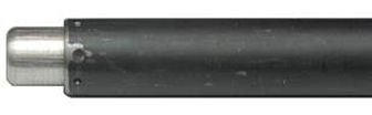
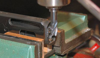
Cutting
the Barrel and Magazine Tube
I chucked
the barrel in my lathe and used a cutoff bit to cut the
barrel down to 16 3/4“. Because of the configuration of my
lathe I couldn’t cut the barrel any shorter.
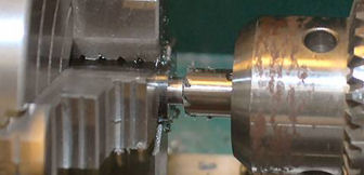
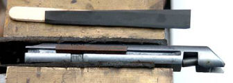
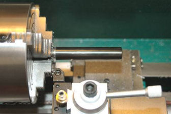
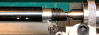
I then
used a 1/2” 79-degree crowning cutter
#080-586-500 with a .30-caliber pilot
#080-686-308 I purchased from Brownells to put an
11-degree crown on the barrel. I used plenty of oil to
lubricate the pilot and cutter. The above photo shows the
end of the barrel, the pilot, and the crowning cutter. The
cutter is pulled away from the barrel to expose the pilot.
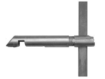
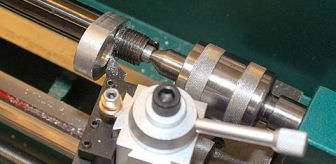
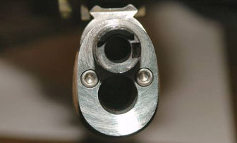
Finally,
I used a brass muzzle lap
#080-764-350 and 400-grit lapping compound to remove any
burrs from the muzzle. I put the lap into my variable speed
drill, applied lapping compound to the end, and with the
drill running at a slow speed, rotated the end of the lap in
the muzzle maintaining the angle shown in the above photo.
This makes the lands and grooves nice and sharp. I cold
blued the exposed metal with
Van’s Instant Gun Blue. I heated the barrel with a hair
drier and applied the cold blue until I got the deep
blue/black color I wanted.
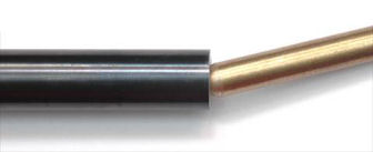
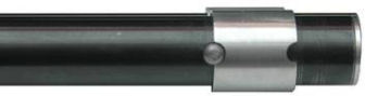
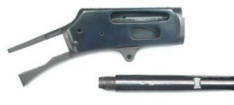
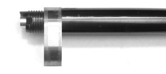
Cutting
the Magazine Tube
I chucked
the magazine tube in my lathe and cut off the front so it
was 1/4” shorter than the shortened barrel. I measured the
location of the original hole for the magazine tube plug and
milled the new hole in the shorter magazine tube.
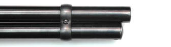
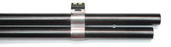
Here is
the shortened barrel and magazine tube. I’m not worried
about any scratches to the bluing because I plan to cover
the rifle with a camouflage pattern. The paint will cover
any imperfections in the bluing.
Installing a Synthetic Youth Butt Stock
My arms are not very long so I have to either cut the
buttstock or install a shorter one for a rifle to fit me
comfortably. I purchased a new Champion synthetic youth
model stock set
#78092 from ebay for a reasonable price. This is also
available from MidwayUSA
#330364. This youth model butt stock is 1 1/4” shorter
than the factory butt stock and comes with a recoil pad
installed.
This butt
stock fit very tightly onto the receiver. I used a Dremel
tool with a narrow grinding stone to relieve each channel
where the receiver tang and trigger guard plate set. I kept
the stone moving so I wouldn’t leave any hollows in the
plastic. When finished, the butt stock still fit snuggly
onto the rifle, but it was easier to remove and install. I
drilled out the butt stock screw hole with a 17/64 drill bit
so I could get the butt stock screw installed.
The
shorter butt stock fits me better, and makes it much easier
for me to lever the action. I could not install the
synthetic hand guard that came with the set because it is
mostly hollow. It needs to be solid to accept the adjusting
screws from the takedown spacer plate, so I will keep the
wooden hand guard.
Adding a
Sling Swivel Stud to the Lower Band
The newer model 336 rifles have a sling swivel stud mounted
to the lower barrel-band. Many years ago, I purchased a
package of 12 Uncle Mike’s® sling swivel studs #2516-0.
They come with a 10-32 x 1/8” threaded end. Apparently
Uncle Mike’s is no longer selling these, but a company
called GrovTec manufactures a similar item available from
MidwayUSA.com
#190531.

I
carefully marked the center bottom of the barrel-band and
milled a 0.159” hole, then tapped the hole with a 10-32
tap. I installed the stud with Loctite red for a permanent
attachment, then filed off the end of the stud until it was
flush with the inside of the band. The band fit perfectly
back onto the fore arm.
Fabricating the Magazine Tube Takedown Parts
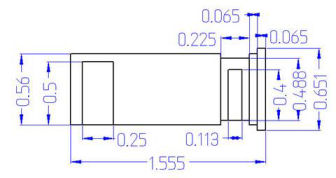
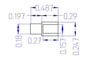
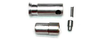
I
fabricated the takedown parts the same as I did for my
Rossi ’92 based on the measurements I made for the 336.
I fabricated a new magazine tube plug out of 6061-T6
aluminum, and the takedown button out of 1/4“ steel round
bar. I milled a 3/16” semi-circle out of the bottom rear of
the new front barrel-band and into the magazine tube, then
milled a 1/4“ hole in the magazine tube plug. I staked the
end of the magazine tube so the follower wouldn’t fall out,
and fabricated a longer magazine tube follower out of
aluminum. With the new magazine tube plug in place in the
shortened magazine tube, and the new follower and shortened
magazine spring, I could still fit 5 cartridges in the
magazine tube, so I reduced the capacity of the tube by only
one cartridge.
Since
there is now nothing holding the magazine tube in place
other than the takedown button, when pulled forward for
takedown, the tube can come completely out of the rifle and
get lost. To prevent this from happening I installed a
magazine tube sling swivel stud just below the front
barrel-band. This stud also gave me something to hold on to
when moving the magazine tube forward.
To
prevent the magazine tube from moving too far backwards when
the rifle is disassembled, I installed a 6-40 filister head
screw in the magazine tube and magazine tube plug in front
of the new barrel-band.
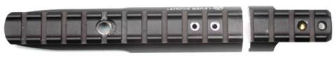
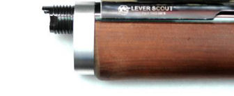
Fitting
an XS Lever Scout Mount
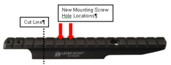
I found a
used XS Lever Scout rail with all mounting hardware on ebay
for $25.00 plus shipping. MidwayUSA has them for $63.90, so
I think I got a great price. Because I’m building a
takedown rifle, this mount cannot be attached to the
receiver.
The XS
Lever Scout rail mounts to the rear sight dovetail with a
dovetail pillar. The instructions state to sand or file the
bottom of the dovetail until the pillar fits into the
dovetail. I placed the bottom on a piece of 600-grit
wet/dry sand paper and briskly moved it back and forth. I
rotate the pillar so I wouldn’t be putting too much pressure
on one side or end. I tried for fit frequently, and sanded
until I could install the pillar into the rear sight
dovetail with finger pressure. I installed the rail onto
the barrel with the pillar screw and nut, and installed the
rear screws into the receiver.
I removed
the butt stock, magazine tube, fore end and front
barrel-band from the rifle, then set it and leveled it in
the machinist vise on my CNC mill. I milled two holes to
accept 6-48 filister-head screws in the locations indicated
by the red arrows in the first figure. The holes for the
screw shanks were 0.112” x 0.325” and were 1/2” apart. The
rail measured 0.192” thick and I wanted the depth of the
screw holes into the barrel 0.133”. The holes for the
filister heads were 0.212” wide by 0.115” deep. I located
the new mounting holes forward by 1/2” because the rear-most
flat of the rail was over the chamber and I wanted thicker
metal for the screw holes in the barrel.
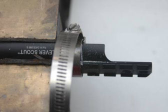
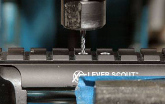
After the
holes were milled I tapped the holes in the barrel with a
6-48 bottom tap and drilled out the center hole in the XS
rail with a #27 drill bit. I cut the rail at the 4th groove
from the rear with a hacksaw. I used a hose clamp to guide
the hacksaw blade. I squared the end with a file and
polished it with 400-grit wet/dry sand paper.
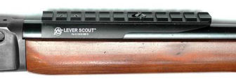
I
installed the rail onto the barrel using two 6-48 x 3/16
filister-head screws from the Pachmayr Master Gunsmith Screw
Kit I purchased from MidwayUSA.com
#967567; everything fit perfectly
Removing
the Barrel
I made a
barrel vise bushing out of aluminum, installed the barrel
vise and bushing onto the barrel with rosin, and installed
the receiver wrench onto the receiver protected with tape.
The barrel came loose with a loud crack.
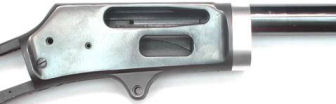
Milling
the Front of the Receiver
I set the
receiver between two oak blocks in my machinist vise and
squared the front. I used a 1/2” square-end bit to mill off
the lip from the front of the receiver. I removed 0.005” at
a time so the bit wouldn’t chatter or move the receiver in
the vise. When I got close to the receiver face I finished
by draw-filing with a bastard file until the lip was gone,
then polished with 400-grit wet/dry sand paper wrapped
around the file. I cold-blued the exposed metal with
Van’s Instant Gun Blue.
Milling a
Step in the Barrel
I
fabricated a mandrel 1.000” long by 0.415” wide out of 1/2”
aluminum rod and used a centering bit to drill a V in the
end for my live center. I inserted the mandrel into the
chamber and mounted and centered the barrel in my lathe. I
turned a step in the barrel that measured 0.815” wide x
0.490” long. The spacer plate is 0.8135” for a press fit.
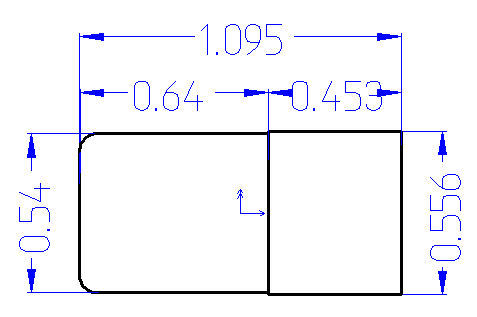
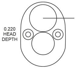
Fabricating a Spacer Plate
I carefully measured the barrel and magazine holes in the
receiver, the space between them, and the distance from the
top of the receiver. I enlarged the barrel hole to 0.8135”
and the magazine tube hole to 0.680”, but left the space
between them the same. The horizontal line extending from
the center of the barrel hole represents a scribe line that
will help me align the extractor notch in the barrel with
the plate.
I traced
around the receiver then scanned the outline into my
computer. I used CorelDraw 12 to create the drawing of the
spacer plate, which I exported to BobCAD-CAM v20 to create
the CAM code for my CNC mill. I milled the plate out of
1/2” 6061-T6 aluminum stock.
Installing the Spacer Plate
I heated
the aluminum spacer with a propane torch, and to my
surprise, it dropped freely over the step in the barrel with
no force required. I made sure the alignment mark I scribed
in the rear of the plate was in the center of the ejector
notch in the barrel. After the plate cooled it was nice and
tight on the barrel.
Fitting
the Spacer Plate
I faced
off the rear of the spacer plate until it fit tightly and
was properly aligned with the receiver. I made shallow cuts
0.005” at a time and installed the receiver frequently until
I got the proper fit. The final cut was only 0.002” to
achieve a tight fit.
I
polished the outside edge of the plate by shoe-shining with
400-grit wet/dry sand paper until it blended with the
receiver.
Cutting
and Installing the Fore End
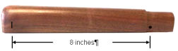
I
measured from the fore end notch in the barrel to the front
face of the spacer plate at exactly 8-inches. I covered the
rear of the fore end with masking tape so the wood wouldn’t
splinter when cut, and marked the fore end 8” from the
barrel band screw hole. I cut the fore end to that mark.
I
installed the fore end onto the rifle and used a #21 drill
bit to drill through the holes in the spacer plate into the
fore end. I opened the holes in the fore end with a #9
drill bit. I tapped the holes in the spacer plate with a
10-32 tap and installed two 10-32 x 3/4” stainless steel cap
screws. The fore end sets nice and tight onto the rifle.
I rounded
the sharp edges left when I cut the fore end to blend with
the spacer plate, then sanded it smooth with 320-grit sand
paper.
Applying
a Camouflage Pattern with Spray Paint
I decided
to camouflage the rifle with spray paint.
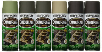
Rust-Oleum® makes a line of flat camouflage spray paint
that can be applied to almost any surface. Amazon.com sells
a camouflage spray pack
#269038 consisting of two cans of forest green, two cans
of earth brown, one can of army green, and one can of
khaki.
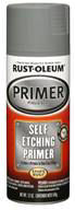 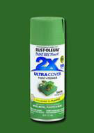 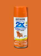 
From my
local Home Depot, I purchased Rust-Oleum self-etching gray
primer
#249322, moss green
#249071, rustic orange
#314753, satin hunter green
#7732830, and matte clear
#285093 spray paints. The primer will cover the entire
rifle, flat white will add texture to the sticks, and the
green and orange paints will provide additional autumn
colors to the leaves. Once the paint cures the matte clear
will protect the finish.
I got
some camouflage ideas by watching a few YouTube videos:
·
https://www.youtube.com/watch?v=jCGIE6dHFtg&t=331s
·
https://www.youtube.com/watch?v=Z5RM-ihRawQ&t=331s#t=59.0098912
·
https://www.youtube.com/watch?v=UgACuGtC3ow
·
https://www.youtube.com/watch?v=d5z2hEWBUT8
·
https://www.youtube.com/watch?v=vJNRGr7r5WY
I really
liked the first video where he used pine needles to make a
“sunlight in a dark forest” effect, which I decided to use
as my background. I also liked the sponge idea to add
texture.
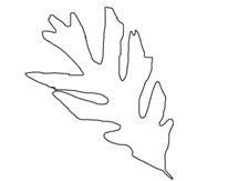
I found a
small leaf stencil on the Internet which I printed onto a
sheet of paper and cut out. This stencil was for the small
orange and green leaves.
I masked
off the areas I did not want to paint. The hardest part was
masking all the holes in the receiver because I didn’t want
to get paint inside. I stuffed foam inside the receiver and
muzzle, and a wooden dowel in the bolt opening. I used
320-grit sand paper to rough up the wood, metal, and
synthetic parts, then cleaned everything with acetone. I
applied a thin coat of Rust-Oleum self-etching gray primer
to the entire rifle and allowed it to thoroughly dry. I
painted everything except the internal parts, screws, and
the lever. To me, the rifle with just the primer looked
ugly!
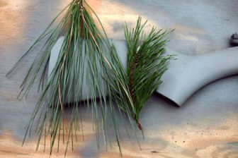
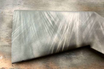
I laid
some pine needles onto the rifle and sprayed with bursts of
the khaki paint. I moved the needles so the resulting
pattern was not going in the same direction and sprayed
again with short bursts of khaki. After one side was
covered, I went back over the same side by laying the
needles in a different direction and spraying with the deep
forest green paint. After each layer of paint, I used a
hair dryer to speed up the drying process so I could apply
the next layer of paint.
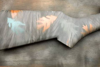
I laid
the small leaf stencil onto the rifle and sprayed with army
green, or orange. After I dried the paint with a hair
dryer, I flipped the rifle over and did the same process
with pine needles, khaki and deep forest green paint, and
the small leaf stencil and orange shaded with earth brown,
and moss green shaded with army green to the other side.
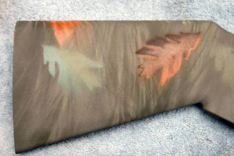
After the
paint dried, I went over one side of the leaf with a darker
color because I wanted the leaves to have some shading. I
used army green on moss green, and earth brown on the orange
leaves.
I flipped
the rifle over and did the same process to the other side.
After the paint cured for about a week I applied two thin
coats of matte clear to protect the paint. After the clear
coat dried I lubricated and reassembled the rifle. I used
Loctite blue on all the screws to prevent them from becoming
loose.
Adding a
Red Dot Sight
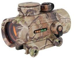
Rather
than add a scout scope I decided to add a red dot sight.
Red dot sights are effective out to 100-yards, which is
probably the farthest I will be shooting this rifle. I
prefer the type of sight that is completely enclosed in a
tube because the tube prevents bright sunlight from washing
out the dot. Unlike a scope, a red dot sight has unlimited
eye relief, which means I can set it anywhere on the rail.
I found a TruGlo red dot sight
#TG8030A with a 5 MOA dot in a Realtree APG finish on
ebay for a very reasonable price with free shipping.

The knobs
that came with the sight were tightened with a supplied
metric allen wrench. Who is going to carry an allen wrench
in the field if you need to remove it and use the ghost ring
sight? I milled a 3/32” slot 0.140” deep in each knob so I
could use a knife blade, coin, or screwdriver blade from a
multi-tool pocket knife to remove the sight. A shot of
khaki and deep forest green covered the bright aluminum
cuts.
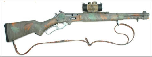
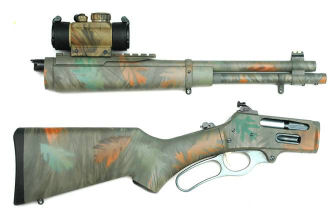
I am very
pleased with the finished result. I guess I should be
careful and not lay my rifle against a tree or I might never
be able to find it! One of my concerns is just how durable
the paint finish will be. I already discovered that Loctite
blue removes the paint, and it scratches easily, but time
will tell.
Adding a
Butt Cuff
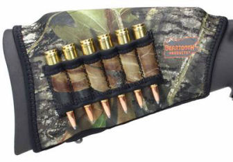
MidwayUSA
sells a buttstock cover by Beartooth Products that comes in
Mossy Oak Break Up
#203692. It includes 5 foam pads of different
thicknesses to raise the comb to fit different shooters for
use with scopes or red dot sights. It also includes 6
cartridge loops for spare ammo.
Bore
Sighting
|
Bore Sight Calculator |
|
Sight Height (inches) |
Angle of Departure |
Sight Position @ 25'
(inches) |
|
1 |
0.063661951 |
0.7 |
|
|
|
|
|
Angle of Departure Calculator |
|
Sight Height (inches) |
Distance to cross line of sight (inches) |
Angle of Departure |
|
1 |
900 |
0.063661951 |
Laser
Bore Sight Data for Peep Sight
I used my
laser bore sight calculator to initially sight in both
the peep sight and the red dot sight. I used the data from
the Remington web site for their .30-30 170 grain Core-Lokt
cartridge. Remington states the muzzle velocity for this
load is 2200 fps with a ballistic coefficient of 0.254.
Using
Sierra Bullets Infinity version 6, with this load sighted in
at 100-yards and the 1-inch fiber-optic front sight, the
bullet would cross the line of sight at 25-yards. When I
entered this data into my calculator it showed that the
front sight would have to be 0.7-inches above the laser dot
at 25-feet, i.e. the laser dot would be 0.7 inches low with
the sights aligned with the center of the target. I
adjusted the receiver-mounted peep sight for this setting.
|
Bore Sight Calculator |
|
Sight Height (inches) |
Angle of Departure |
Sight Position @ 25'
(inches) |
|
1.84 |
0.06507666 |
1.5 |
|
|
|
|
|
Angle of Departure Calculator |
|
Sight Height (inches) |
Distance to cross line of sight (inches) |
Angle of Departure |
|
1.84 |
1620 |
0.06507666 |
Laser
Bore Sight Data for Red Dot Sight
The
TruGlo red dot sight sets about 1.84-inches above the bore.
The bullet would cross the line of sight at 45-yards. Using
this data showed that the red dot would have to be
1.5-inches above the laser dot at 25-feet, i.e. the laser
dot would be 1.5 inches low with the sight aligned with the
center of the target. I adjusted the red-dot sight for this
value.
These
values should get my shots on paper at 100-yards. I started
at 50-yards and adjusted my sights to be 1/2"-low, which
brought my shots right on at 100-yards.
Summary
The takedown lever-action is not a new concept, although it
has been made popular by Wild West Guns with their Copilot,
which is a modified Marlin lever-action rifle. I converted
my Rossi ’92 .45 Colt rifle into a takedown rifle (refer to
my article
Building a Lever-Action Takedown Rifle) which was
based on the article A Takedown Rifle found in The
NRA Gunsmithing Guide – Updated published in 1982, so
the process has been around for a while.
After all the work was
completed and with the red-dot sight installed, the rifle
weighed 7.25 pounds; just under Col. Cooper's requirement.
Marlin
336 Year of Manufacture
The following table can be used to date the year of
manufacture of a Marlin 336. It is also valid for
determining most other Marlin firearm build dates from 1946
to the present.
Marlin
year of manufacture maybe determined from the following
table of letter/numeral prefixes to the serial number:
|
Date |
Prefix(s) |
|
|
Date |
Prefix(s) |
|
|
Date |
Prefix(s) |
|
|
1946 |
C |
|
|
1955 |
M |
|
|
1964 |
Y, |
Z |
|
1947 |
D |
|
|
1956 |
N |
|
|
1965 |
AA |
|
|
1948 |
E |
|
|
1957 |
P |
|
|
1966 |
AB |
|
|
1949 |
F |
|
|
1958 |
R |
|
|
1967 |
AC |
|
|
1950 |
G |
|
|
1959 |
S |
|
|
1968 |
AD, |
68 |
|
1951 |
H |
|
|
1960 |
T |
|
|
1969 |
69 |
|
|
1952 |
J |
|
|
1961 |
U |
|
|
1970 |
70 |
|
|
1953 |
K |
|
|
1962 |
V |
|
|
1971 |
71 |
|
|
1954 |
L |
|
|
1963 |
W |
|
|
1972 |
72 |
|
Starting
in 1973, the year of manufacture can be determined by
subtracting the first two digits of the serial number from
100: Example: SN 2512345 would have been made in 1975 [100 -
25 = 75].
|