Building a Lever-Action Takedown Rifle
by Roy Seifert
Click here to purchase a
CD with this and all Kitchen Table Gunsmith Articles.
Disclaimer:
This article is for entertainment only and is not to
be used in lieu of a qualified gunsmith.
Please defer all firearms work to a qualified
gunsmith. Any loads
mentioned in this article are my loads for my guns and have
been carefully worked up using established guidelines and
special tools. The
author assumes no responsibility or liability for use of
these loads, or use or misuse of this article.
Please note that I am not a professional gunsmith,
just a shooting enthusiast and hobbyist, as well as a
tinkerer. This
article explains work that I performed to my guns without
the assistance of a qualified gunsmith.
Some procedures described in this article require
special tools and cannot/should not be performed without
them.
Warning:
Disassembling and tinkering with your firearm may
void the warranty. I
claim no responsibility for use or misuse of this article.
Again, this article is for entertainment purposes
only!
Tools
and firearms are the trademark/service mark or registered trademark
of their respective manufacturers. All tools were
purchased from Brownells
unless otherwise indicated.
Introduction
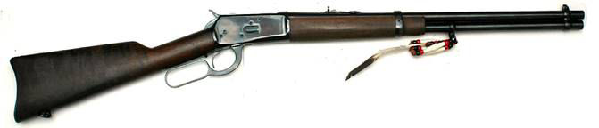
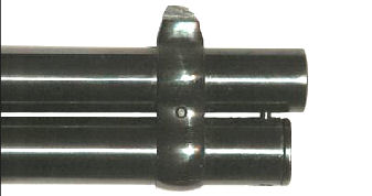
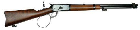
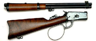
When I started Cowboy Action Shooting™ in 2000, my first
lever-action rifle was a Rossi ’92 SRC in .45 Colt. I
believe SRC stands for Saddle Ring Carbine, but my rifle
didn’t come with a saddle ring. Because so many other
shooters in our club had the same rifle I added the beads
and feather to the front sling swivel so I could tell which
one was mine when lined up in the rifle rack.
The Rossi
‘92 SRC is a modern copy of the Winchester model 1892
lever-action rifle; the iconic rifle used in many western
movies and TV series. My rifle didn’t have the
receiver-mounted safety or rebounding hammer; it was built
as John M. Browning had originally intended. I used this
rifle in cowboy matches for years, but retired it in favor
of a Marlin 1894 Cowboy in .45 Colt. The stock on my rifle
is pretty beat up from years of banging around in gun carts
and range racks, but I never could part with it because I
like the nostalgia and action of the rifle. Now it’s time
to have some fun and improve my gunsmithing skills by
converting it into a takedown rifle.
I found
two articles on the Internet on how to perform this
conversion:
http://rvbprecision.com/shooting/rossi-1892-winchester-take-down-conversion.html
http://www.homegunsmith.com/cgi-bin/ib3/ikonboard.cgi?act=ST;f=3;t=19176;hl=takedown
Both are
based on the article A Takedown Rifle found in The
NRA Gunsmithing Guide – Updated which I used as my
primary guide for this project.[i]
Unfortunately, all the articles left out some steps which I
had to improvise along with way.
Conversion Plan
To convert this rifle into a takedown rifle I performed the
following steps, some of which were not required for the
conversion, but were changes I wanted to make to the rifle:
1.
Fabricate a new front barrel-band with integral dovetail
(not required for the conversion)
2.
Install a front sight with green fiber optic rod (not
required for the conversion)
3.
*Fabricate a longer magazine tube plug
4.
*Fabricate a takedown button
5.
Mill the button hole in the magazine tube and front
barrel-band
6.
Clean the magazine tube (not required for the
conversion)
7.
Crimp the end of the magazine tube so the follower will not
come out when taking apart the rifle
8.
*Fabricate a longer follower (not required for the
conversion)
9.
Mill two notches in the magazine tube for the two
barrel-band screws so it can move forward
10.
Completely disassemble the rifle and unscrew the barrel from
the receiver
11.
Mill the front of the receiver flat and polish
12.
*Turn down a step on the barrel behind the threads
13.
Fabricate a spacer plate
14.
Press the spacer plate onto the barrel
15.
*Face off the rear of the spacer plate so it sits flush
against the receiver
16.
Fit the spacer plate to the receiver
17.
Modify the fore end so it will fit on the barrel and spacer
plate
18.
Install a large loop lever (not required for the
conversion)
19.
Finish the aluminum parts (not required for the
conversion)
20.
Refinish the wood (not required for the conversion)
21.
Install a tang peep sight (not required for the
conversion)
Lathe
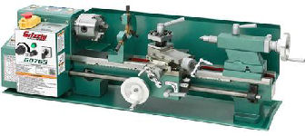
*The
steps above marked with an asterisk required the use of a
lathe. I purchased a Grizzly G0765 7” x 14” bench-top lathe
which, with some modifications, worked very well for this
project. Purchasing my bench top mill/drill back in 2002
got me started into real gunsmithing, and the lathe will
further improve my knowledge, skills and capabilities. I
purchased a few books on how to use a lathe to help me
learn, and found some great “how-to” videos on You Tube:
https://www.youtube.com/watch?v=Za0t2Rfjewg
https://www.youtube.com/watch?v=jXET1-g6CJA
https://www.youtube.com/watch?v=3ue8XtStUBA
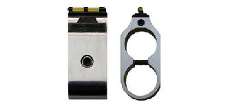
Front
Barrel-Band
The original front sight was an integral part of the front
barrel-band and was narrow. I wanted to install a green
fiber-optic front sight, and quickly change out front sights
which is why I decided to fabricate a new front
barrel-band.
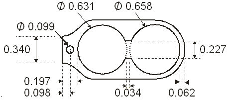
I carefully measured the diameter of the barrel and the
magazine tube holes in the original barrel-band, and
measured the distance between the bottom of the barrel and
top of the magazine tube at the location of the original
barrel-band. I increased the diameter of the magazine tube
hole so the magazine tube wouldn’t bind when the mounting
screw was tightened; it must be able to move forward. I
used CorelDraw 12 to produce the initial design for the new
front barrel-band, then exported the drawing to BobCAD CAM
v20 to produce the G-code for my bench-top CNC mill.
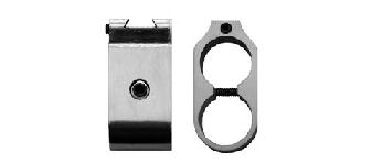
I fabricated the new front barrel-band out of 3/4” 6061-T6
aluminum. I then milled a 3/8” wide x 0.100” deep x
65-degree dovetail for the new sight using a 65-degree
dovetail cutter I purchased from Brownells
#080-621-305.
The dovetail cutter was only 0.300 wide, so I opened up the
dovetail by moving my milling machine table 0.037” on either
side of center, then finished with a 65-degree dovetail file
I purchased from Brownells
#080-648-165
so the sight would move freely. I drilled and tapped a 6-32
hole for a set screw in the front of the barrel-band to hold
the front sight in place. A drop of Loctite blue prevents
the screw from coming loose. By loosening the set screw, I
can easily change sights.
I drilled a center hole with a #43 drill bit through both
sides to accept a long, 4-40 hex-head screw. I tapped one
side with a 4-40 tap, and drilled the other side larger with
a #32 drill bit. I then used a 1/4” square end milling bit
to mill a countersink so the hex head would set flush with
the side. This screw mounts the barrel-band to the rifle.
I used my Dremel tool and a cutoff wheel to cut the end of
the screw so it wouldn’t protrude from the side of the band,
then polished and cold-blued the cut end.
Front Sight
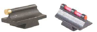
I ordered a Williams Fire Sight 312M fiber optic front
sight from MidwayUSA
#865025.
This sight has a base width of 0.340” which was the
dimension I used for the top of the barrel-band, and length
of 3/4” which fit the new barrel-band perfectly. This sight
came with a red rod, which I hate because for me, red tends
to blend in with the background and disappear. Many years
ago, I ordered both red and green 1/16” fiber optic rods
from
Oakridge
Hobbies.
Although the package said 1/16”, they actually measured
0.060” which was the same size as the rod that came with the
Williams Fire Sight.
I used a razor blade to cut through the red rod in the
sight and removed each piece. I cut a piece of green rod
13/16” long and held one end close to a flame, not in the
flame. This created a ball of plastic at the end. I
inserted the end into the sight and cut the opposite end
1/16” away from the sight. I held the balled end of the rod
against the sight with my finger and held the straight end
close to a flame, again not in the flame, which created a
plastic ball on the opposite end. The two balls hold the
rod in place. I didn’t want to touch the flame to the
plastic rod because this would burn the rod and crystalize
the plastic which reduces its light transmission capability.
Cowboy Action Shooting™ rules do not allow fiber optic
sights so I also ordered a Williams 312M beaded front sight
from MidwayUSA.com
#358804.
If I want to use or loan my rifle for a cowboy match I just
switch out the sights. By the way, these sights came with a
tapered dovetail. I used the 65-degree dovetail file to
slightly straighten the taper so the sight would fit in the
dovetail in the barrel-band.
The original front sight measured 0.400” from the top of
the barrel. The Williams 312M sights measure 0.312” from
the bottom of the dovetail, but the sight itself measures
0.212”; the depth of the dovetail measures 0.100”. The new
sights now sit 0.409” above the barrel (0.197” barrel-band
plus 0.212” sight). To maintain the same sight height, I
would have needed a 0.303” front sight, but the Williams
sights only came in 0.290” or 0.312” heights. I decided to
go higher because I plan to install a Marbles tang peep
sight which I can adjust for the increased height of the
sight. Also, some of my heavier loads shoot high so I
needed the taller front sight. It’s usually easier to
adjust a sight higher than lower.
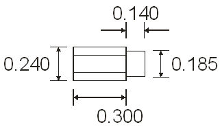
Magazine
Tube Plug
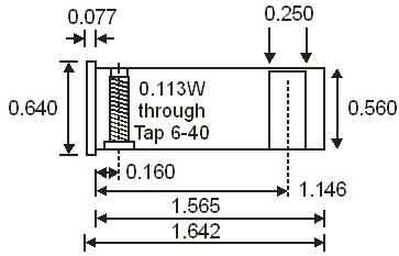
Before
doing any lathe work on the rifle barrel, I wanted to get
some practice to develop my skills. I had some 7/8” round
aluminum bar stock I had purchased from
OnlineMetals.com which I used to fabricate the new
magazine plug to the above dimensions. These were based on
the measurements for my rifle with the new front barrel-band
in place. The 6-40 threaded hole at the front of the plug
is for the plug screw that holds the plug in the magazine
tube. The original screw protruded into a hole drilled into
the barrel to prevent the magazine tube from moving or
rotating, but this will no longer be needed because of the
takedown button. The original screw had a 6-48 thread, but
I didn’t have a 6-48 tap, so I used 6-40 instead.
The 1/4”
hole at the other end of the plug is for the takedown
button. This button protrudes from a hole in the magazine
tube and sets in a notch milled in the rear of the front
barrel-band and has two functions; one, it prevents the
magazine tube from rotating and moving forward when the
rifle is assembled, and two, when pressed it allows the
magazine tube to move forward for disassembly.
Even
though I did a lot of research on how to run a lathe,
because I had never used one before, my first magazine tube
plug was a throw-away, which I expected. As I got close to
the diameters I needed for my part, I neglected to measure
so they were undersized. The second plug I produced was
very accurate because as I got close to the diameter I
needed, I measured frequently and adjusted my lathe to cut
accordingly.
I
inserted the new plug into the end of the magazine tube and
marked the location of the screw hole with a felt-tip pen.
I chucked the plug into the rotary axis of my bench-top CNC
mill and located the center of the plug. I used a 3/32”
square end milling bit to plunge-mill half-way through the
plug at the location of the plug screw. I rotated the
rotary axis 180-degress and plunge-milled through the other
side of the plug. I then milled a countersink for the screw
head 0.200” wide by 0.055” deep.
I used a
#33 drill bit to ream out the hole, then tapped the hole
with a 6-40 tap. I didn’t tap completely through the hole
because I wanted to leave some metal for the narrow end of
the screw.

I
fabricated a new magazine plug screw from a 6-40 x 1-inch
fillister head screw. I used my Dremel tool with a cutoff
wheel to cut the screw, then used my lathe to remove the
threads from the last 1/3 of the screw and reduce the
diameter of the head. I polished and cold-blued the exposed
areas of the screw.
To modify
the screw, I fabricated a screw holder out of a piece of
scrap 7/8” aluminum rod. I used a #33 drill bit to drill a
hole through the center of the scrap, then milled a 1/4”
hole half-way through. I tapped a 6-40 hole in the
remaining half. I used this holder when I cut the end of
the screw, then chucked it into the lathe to remove the
threads. I turned the screw around in the holder and used
the lathe to turn down the head so it would fit in the
magazine tube.
I milled
a 1/16” wide slot 0.080” deep and 1/2” long in the front
face of the plug. This is for a screw-driver blade to
facilitate removal of the plug so I can clean the magazine
tube.
Takedown
Button

I turned
the takedown button from a piece of 1/4” aluminum rod, which
actually measured 0.243”. I plunge-milled a 1/8” hole in
the end, then opened it up with a #24 drill bit to accept a
0.125” OD x 5/8” spring from Brownells spring kit #69
#025-069-000. I made the front part of the button
0.002” smaller than 3/16” so I could use a 3/16” square end
milling bit for the button hole in the magazine tube and
front barrel-band.
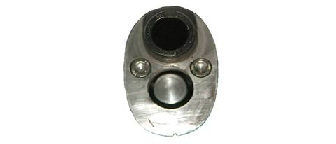
Milling
the Button Hole
I removed
the magazine tube from the rifle and installed the new
magazine tube plug. I wrapped a piece of tape around the
plug so it would fit tightly in the tube. I installed the
new barrel-band onto the magazine tube and tightened the
band screw so the barrel-band and plug would not move. I
mounted the band into my machinist vise, and centered a
3/16” square-end bit so it would mill a half-circle on the
bottom-rear of the barrel-band. I plunge-milled the button
hole in the front barrel-band and magazine tube with a 3/16”
square end bit and made sure I plunged at least 2/3 through
the plug.
I removed
the plug from the magazine tube, and finished milling the
button hole to 0.250” x 0.530” deep. I inserted the button
and spring into the button hole and found that the front
wouldn’t sit flush with the plug. I removed 2 coils from
the spring and now it fit.
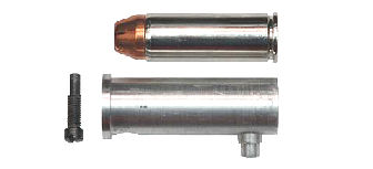
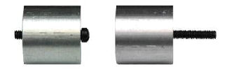
Above is
a photo of the completed plug and new screw next to a .45
Colt cartridge. You can see that the longer plug will
reduce the magazine tube capacity by one round, but I can
still load 10 + 1 making it suitable for cowboy shooting.
I
lubricated the button with a little synthetic grease,
inserted it into the hole in the plug, then inserted the
plug into the magazine tube until the button popped through
the button hole in the magazine tube. Everything fit
perfectly.
Cleaning
the Magazine Tube
When I removed the magazine tube to perform this work, I
discovered that it and the magazine spring were beginning to
rust. I took some 000 steel-wool and gun oil and ran it
over the spring and through the magazine tube to remove the
rust, then left both with a thin coat of oil to prevent
further rusting. I also cleaned leftover soot in the
receiver-end of the magazine tube and follower. This came
from shooting light, target loads that didn’t completely
seal the chamber.
After
shooting a rifle or shotgun that has a magazine tube, part
of my cleaning routine is to also clean and oil the magazine
tube and spring to prevent rust from forming. When I
purchased my Winchester ’97 shotgun the magazine tube spring
was rusted through in two places, and the magazine tube
itself had some heavy pitting due to rust from years of
neglect (refer to my article
Modifying a Winchester 97 for Competition).
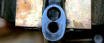
Crimping
the Magazine Tube
The receiver end of the magazine tube must be crimped so the
follower doesn’t fall out and jam the rifle when being
disassembled. Only one of the Internet articles described
how to do this, and the NRA guide had no suggestion, so I
came up with my own idea.

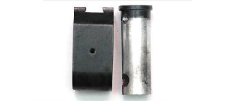
I thought
the best way to accomplish this was to stake dimples in the
magazine tube. Using my new lathe, I made an anvil out of
7/8” aluminum rod. The anvil had three steps; the inner
widest step was the same diameter as the outside of the
magazine tube, the center step was the same diameter as the
inside of the magazine tube and prevented the tube from
crushing when I performed the staking, and the outer-most,
narrowest step allowed me to remove the anvil from the
magazine tube. The anvil fit into the end of the magazine
tube and had four grooves, one for each dimple. I milled
the four grooves to the same depth as the narrowest step.
These grooves allowed me to remove the anvil after staking.
I marked
the magazine tube 1/8” from the end. I placed the anvil
into the end of the magazine tube and used a prick punch to
punch a dimple on the line at the location of each groove.
I was surprised just how soft this metal was and how easy it
was to punch. After punching the four dimples I had to use
a rod to push the anvil out of the magazine tube.
The anvil
prevented the magazine tube from being crushed or bent
during the staking process, so the tube fit back into the
receiver with no problems. The four dimples now hold the
follower in place for disassembly.
Longer
Follower

The
original follower now set 1/8” deeper in the magazine tube.
Although this didn’t seem to affect function when I tested
the rifle with dummy rounds, I wanted the follower to push a
cartridge completely out of the magazine tube, so I turned a
new follower that was 1/8” longer than the original. (Man,
I’m having fun with my new lathe!)
I again
used a piece of 7/8” aluminum rod and turned the new
follower to the same diameters as the original. The inside
diameter of the original follower measured 0.455”. I
drilled out the center with a 29/64” drill bit which
measured 0.453”. This slightly smaller diameter didn’t seem
to make much difference; the magazine spring fit with just a
small amount of friction allowing me to remove the follower
just by pulling on the spring. I used a file to put a
slight taper on the front of the follower like the
original. The front of the new follower now extends
slightly out of the magazine tube as the original follower
did. I tested the rifle with dummy cartridges and they fed
with no problems.
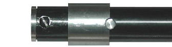
Milling
Takedown Notches in the Magazine Tube
Normally,
the magazine tube is held in place by the two barrel-band
screws, and the magazine tube plug screw. To allow the
magazine tube to move forward for disassembly I cut the new
magazine tube plug screw short so it wouldn’t touch the
barrel. The barrel-band screws mate with two notches cut in
the barrel and magazine tube; the notches prevent the tube
from moving. Because I wanted the magazine tube to move
forward, I needed to extend the notches just in the magazine
tube. I did not want to extend the notches in the barrel
because I didn’t want the barrel-bands to move.
I found
that I only had to move the magazine tube one-inch forward
for the follower to clear the receiver. I set the magazine
tube in the machinist vise and used a 1/8” milling bit to
mill a one-inch notch 0.030” deep. I repositioned the tube
to mill the other notch to the same dimensions. I was
careful not to tighten the vise too much because I didn’t
want to crush or distort the fragile tube.

Once both
notches were milled I cold-blued the exposed metal and
coated them with oil. The notch looks rough in the above
photo because I didn’t polish the metal after milling. I
reassembled the rifle, tightened down both barrel-band
screws, and tested the magazine tube. When I pressed the
button, I could pull the magazine tube forward; sweet
success!
Rifle
Disassembly

I had no
problems disassembling the rifle since I had done it before,
but this was the first time I had removed the barrel from
the receiver. I fabricated an aluminum bushing for my
barrel vise so I could unscrew the barrel. I placed two
marks on the barrel 1-inch apart. The barrel measured
0.820” and 0.771” at the marks. Using my
barrel taper calculator, the barrel taper was
1.403-degrees. I have several bushings for different rifles
and handguns so I stamped the model on the receiver-end of
the bushing.
I put
masking tape on the receiver so the receiver wrench wouldn’t
mar the bluing, and installed the receiver wrench. Because
the receiver was square and flat I didn’t have to purchase a
special wrench. I sprinkled rosin I purchased from
Brownells
#083-016-100 on the inside of the bushing and inside the
barrel vise and installed the bushing onto the barrel. I
mounted the barrel vise in a well-supported bench vise and
removed the barrel. To get the extra leverage I needed to
unscrew the barrel, I used a 24-inch piece of steel pipe on
the handle of the receiver wrench.
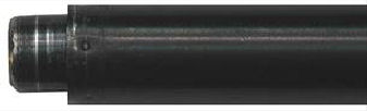
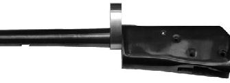
Milling
the Front of the Receiver
To get the spacer plate to fit flush against the face of the
receiver I had to remove the lip that the fore end set in.
I cut two pieces of 1 x 2 wood, 3 1/2” long to serve as
spacers for the receiver. The sides of the receiver are not
perfectly flat; there are two flares at the front and rear
for the butt stock and fore end.
I mounted
the receiver in my machinist vise using the 1 x 2 spacers.
I used a 1/2” milling bit to remove the lip 0.010” at a
time. You can see in the above photo where I’ve started to
mill the lip and left a ledge in the untouched portion.
I milled
the lip until there were just a few thousandths left, then
used a flat bastard file to draw file the rest. I was
careful to keep my file flat so I would keep the face of the
receive flat.
I
polished the face with 400-grit wet/dry sand paper wrapped
around the flat file, then cold-blued the exposed metal.
The above photo shows the result. By the way, I’m using
Brownells Oxpho-Blue Crème
#082-124-004 for all my cold bluing.
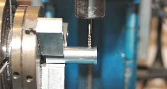
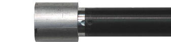
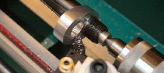
Turning Down a Step on the Barrel
Because the bed of my lathe is a little less than 17-inches,
my 20-inch rifle barrel would not fit, therefore I had to
install it through the bore of the headstock. The headstock
has a 3MT (Morse taper) which allows material up to 0.780”
in diameter through the bore. My lathe came with a 3-jaw
scroll chuck, which means the jaws open and close together
with the chuck key. Unfortunately, the center hole of this
chuck is only 5/8-inches, which is not enough for the ‘92
rifle barrel.
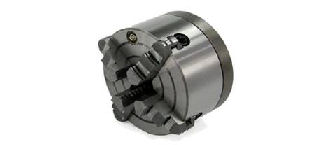
I purchased a 5-inch, 4-jaw, independent chuck with adapter
plate from Little Machine Shop
#2346. The adapter plate allowed me to mount this large
chuck on my small mill. This is an independent chuck which
means each jaw works independently from the others, i.e.
each jaw is adjusted individually with the chuck key. The
scroll chuck is ok if I want to fabricate something from
scratch where I don’t care about runout, but the 4-jaw chuck
can be adjusted to eliminate runout, which is important when
working on the rifle barrel. The bore of this chuck is
1.180” which is larger than the bore of the headstock, so it
should be ok for a tapered rifle barrel.
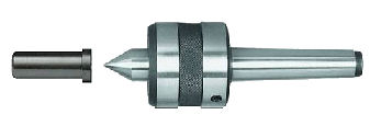
Long work pieces, like a rifle barrel, need to be supported
at a minimum of two points to prevent it from wobbling. I
didn’t want to use the steady rest that came with the lathe
because it didn’t have bearings and I didn’t want to leave a
mark on the barrel. I fabricated a mandrel which fit into
the chamber of the barrel. In the rear of the mandrel I
drilled a 60-degree hole using a center drill for my live
center in the tailstock.
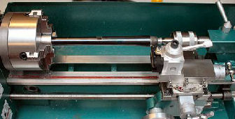
I fabricated another bushing that fit onto the barrel
9-inches from the chamber out of 3/4“ aluminum. The barrel
measured 0.690” and 0.684” at that point. Again, using my
barrel taper calculator, the taper came out to
0.229-degrees. With the bushing on the barrel and in the
4-jaw chuck, and the mandrel in the tailstock of the lathe,
the barrel was now supported at two points by the chuck and
the tailstock.
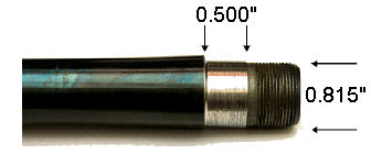
I turned down a step in the barrel that measured 1/2” wide
by 0.8155” in diameter. I’m using 1/2” aluminum bar stock
to fabricate the spacer plate. In the above photo, the step
does not look centered on the barrel. This is because the
barrel had a flat spot on the bottom so it wouldn’t
interfere with the magazine tube.
Fabricating a Spacer Plate
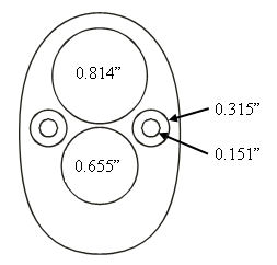
I traced around the face of the receiver, then scanned the
tracing into CorelDraw 12 to create a line drawing of the
outline. I carefully measured the receiver holes and placed
them accordingly in the outline drawing. I made the barrel
hole 0.814” in diameter so it can be pressed onto the barrel
flat. The magazine tube hole I made 0.655” in diameter.
The two holes on each side are for 10-32 hex-head cap
screws. These screws hold the fore end in place, and
provide adjustment if the spacer plate becomes loose over
time. The NRA article recommended using 1/4-20 screws, but
I thought they would be too large so I used 10-32 screws
instead.
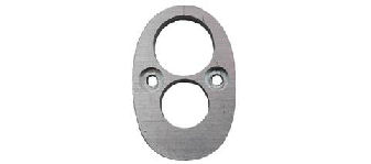
I exported the line drawing to BobCAD-CAM v20, and from that
I created the G-code for my CNC mill. I milled the spacer
plate out of 1/2” 6061-T6 aluminum bar stock. Before
cutting out the plate, I marked the center at the top of the
plate. This helped me align the extractor groove in the
barrel to the top of the plate.
Pressing the Spacer Plate onto the Barrel
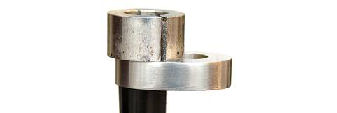
I heated the spacer plate with a propane torch and pressed
the plate onto the barrel using the barrel bushing I used to
remove the barrel from the receiver. Once the plate was
heated, I placed the bushing on top of the plate and used a
rubber mallet to strike the bushing and press the plate onto
the barrel. Each time I heated the plate I was able to
press it about 1/8”. After four cycles of heating and
pressing the plate was seated onto the barrel.
After the plate was seated I noticed the mark at the top of
the plate was not centered over the extractor groove in the
barrel. I again heated the plate with a propane torch and
used the mallet to rotate the plate on the barrel until the
extractor groove was centered on the mark in the plate.
Facing Off the Plate
The plate was thicker than the step on the barrel, which
meant the barrel could not rotate into the proper position.
To get the barrel to rotate to the proper position I needed
to remove metal from the remaining barrel shoulder and the
rear of the plate.
I set the barrel in the lathe as I did before and removed a
small amount of metal from the rear of the spacer plate. I
moved the tailstock out of the way and screwed on the
receiver to test for fit. I performed this remove metal and
fit procedure many times until the plate fit snuggly and was
properly aligned on the receiver.
Fitting the Spacer Plate
I wanted the spacer plate to fit flush with the edge of the
receiver. With the spacer plate properly aligned, I marked
the rear face with a blue marker and traced around the edge
of the receiver with a scribe. This left a mark in the blue
which corresponded to the outline of the receiver face.
I put tape on the barrel threads and on the barrel in front
of the spacer plate. I used a flat bastard mill file to
file the edge of the spacer plate down to the line. I had
to clean my file after 3 or 4 strokes to prevent the teeth
from becoming full and gouging the soft aluminum. After the
spacer plate was filed I used 400-grit wet/dry sand paper to
“shoe-shine” around the outside edge until it was polished
smooth.
Modifying the Fore End
I cut the
end of the fore end with my miter saw, then used my belt
sander to trim the end until it fit. I positioned the fore
end onto the rifle, then used a #21 drill bit to drill
through the adjusting screw holes in the spacer plate into
the fore end.
After I
drilled the holes in the fore end, I tapped the adjustment
holes in the spacer plate with a 10-32 tap. I tapped the
holes after drilling the fore end because I didn’t want to
damage the threads when drilling the holes. I installed two
10-32 x 7/8” stainless steel hex-head screws into the spacer
plate. As the screws mated with the fore end they tapped
threads into the wood. The fore end is now nice and tight
with these screws in place.
Installing a Large Loop Lever
My rifle originally came with a large loop lever which I
found difficult to operate quickly for cowboy shooting. I
replaced it with a standard lever which I could operate much
more quickly, but now I wanted to put the large loop lever
back on the rifle.

I used a
punch to remove the friction stud stop pin (47) from the
lever, which allowed me to remove the friction stud (45) and
friction stud spring (46) from the lever. I installed these
parts into the large loop lever, then installed the lever
into the receiver.
The
secret to using the large loop lever is to push your hand
forward so the loop rides along the front edge of your hand
which opens the action. Then close the action by pressing
the loop towards the butt stock as normal.
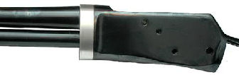
Finishing
the Aluminum Parts
I didn’t
want the bright aluminum parts to show, so I blacked the
aluminum with Birchwood Casey Aluminum Black. This product
works like cold-bluing for aluminum. I cleaned the parts
with acetone, then applied the aluminum black with a cotton
swab. I let the solution set for 60-seconds, then rinsed it
off with cold water. After the part was dry I sprayed it
with two coats a high gloss clear coat to protect the
finish. It doesn’t look like blued steel, but it does look
nice.
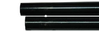
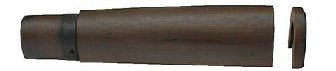
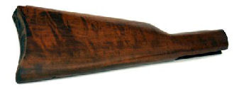
Refinishing the Wood
The butt stock and fore end had some sort of dark stain
which covered the beauty of the walnut. I used Bix paste
stripper to remove the old finish from the wood. I applied
4 coats of the stripper, then washed the wood with water and
scrubbed with a Scotch-Brite scouring pad.
After the
wood was dry I steamed out the dents using an iron and a wet
towel. This not only raised the dents, but it also raised
the grain. I used 400-grit wet/dry sand paper to smooth the
wood and remove the “feathers” that were raised by the
steaming process.
I allowed
the wood to completely dry overnight, then applied three
coats of Birchwood Casey Tru-Oil. I allowed the wood to dry
for 6 hours between each coat. Tru-Oil is my favorite
finish because it’s easy to apply, and if the wood gets
scratched or damaged, it’s easy to repair and apply another
coat. The butt stock is some sort of dark, “tiger” walnut.
As you can see in the above photo, you can now see the
beautiful grain and patterns in the wood.

I have
never been able to use a complete bottle of Tru-Oil because
once the bottle is opened and air gets in, it dries out. I
found a product called Bloxygen on Amazon.com that prevents
finishes like Tru-Oil from skinning over or drying out.
After I apply a coat of Tru-Oil, I spray some Bloxygen into
the bottle before closing the lid. Bloxygen works so well
that I have been using the same 8-ounce bottle of Tru-Oil
for years without having it dry out.
Installing a Tang Peep Sight
I won’t go into the details of installing a tang peep sight
to this rifle because I have already written an article
(refer to my article
Adding a Tang Peep Sight to
a Lever-Action Rifle). However, the Rossi
rifles use different tang screws depending on when and where
they were manufactured. My particular rifle requires a
10-32 x 1 3/4” tang screw to mount the peep sight. I
purchased a Marbles tang peep sight for a Rossi ’92 from
MidwayUSA.com
#140573. This sight also fits a Winchester ’94.
Apparently, the newer Rossi ’92 rifles require a M5-8 metric
tang screw, which is the screw provided in Marbles screw set
995002. This is the screw set Marbles says will fit the
Rossi. My older Rossi required a 10-32 x 1.75 tang screw so
a quick call to Marbles and they sent me the correct screw.
Conversion Completed
At this
point the conversion is complete. I replaced the sling
swivels on the magazine tube and butt stock with sling
swivel studs and quick-detach sling swivels which are very
convenient and easy to remove a sling from this take-down
rifle.
To
disassemble the rifle, I open the action, press the button
behind the front barrel band, pull the magazine tube
forward, and unscrew the barrel. To reassemble the rifle, I
open the action, screw the barrel onto the receiver until
the spacer plate is snug and aligned properly, press the
takedown button, and push the magazine tube in place until
the button locks in the notch behind the front barrel band.
Summary
After watching the Wild West Guns (WWG) TV series Wild
West Alaska and seeing their Copilot rifle, which is
nothing more than a converted Marlin, I wondered if I could
do the same conversion. My philosophy is if someone else
can do it, I can learn how to do it myself. The Copilot
does not have interrupted threads on the barrel and
receiver, which means you attach or detach the barrel with
multiple turns. I decided to do the same with my rifle to
reduce machining time. My Rossi ’92 requires 11 turns to
disassemble/assemble the rifle.
To
maintain the full magazine capacity of the original rifle,
WWG replaces the magazine plug screw with a thumb screw. I
personally don’t like that blob of metal hanging down below
the rifle; I think it detracts from the clean lines and look
of the original rifle, which is why I like the button plug.
As mentioned before, this reduced the capacity of my rifle
from 11+1 to 10+1, but that is acceptable and I can still
use the rifle for cowboy shooting.
.45 Colt,
or “Long Colt”, has always been my caliber of choice for
Cowboy Action Shooting™ and field use. Modern reloading
manuals provide recipes for more powerful loads approaching
or exceeding the .44 magnum suitable for use in Ruger or
Contender firearms. Some ammunition manufacturers are also
producing heavier loads in .45 Colt. The ’92 action is also
strong enough to handle these loads, which makes this
takedown conversion the perfect backpack companion.
The WWG
Copilot sells for $3,277 at the time of this writing.
Chiappa Firearms of Italy is building a series of ’92
takedown rifles which are imported by
Taylor’s and Company. At the time I wrote this article,
their prices started at $1,363 up to $1,483 depending on
what you wanted. A quick search of
Gunbroker.com shows Rossi ’92 rifles are available from
$300 to $600+. I think I paid $410 for my rifle new, plus
about $200 in upgrades for this project, the right tools,
some time and elbow grease and I have a neat takedown
rifle. This was not only a fun project, but I learned new
skills with my new lathe.
My rifle
did not have the same dimensions as the Winchester ’94 rifle
used in the NRA article; my rifle was a bit smaller. If I
was to perform this conversion on a different lever-action
rifle I would have to perform all the measurements over
again to ensure everything would fit.
Addendum
I decided not to refinish the rifle since I thought the
bluing already looked nice. However, I didn’t think the
painted aluminum matched the blued finish, so I decided to
re-make all the parts in cold-rolled steel so I could blue
them to match the rifle. I considered my aluminum parts as
practice, and made a few changes when I made the parts in
steel. I purchased the steel I needed from
OnlineMetals.com, which is my source for the steel,
aluminum and brass that I use for my projects.
As I
completed each part, I polished it with 400-grit wet/dry
sand paper then degreased it with acetone. For small parts
and touch-up I used Brownells Oxpho-Blue Creme
#082-124-004 to cold-blue the parts. I prefer the creme
because it sticks to the part. I heated the part in a small
toaster oven to 120-degrees Fahrenheit for 10 minutes, then
applied the Oxpho-Blue. I wiped it off after 60-seconds,
then buffed with #000 steel wool. After 3 or 4
applications, the parts took on a deep blue-black color that
closely matched the original bluing on the rifle.
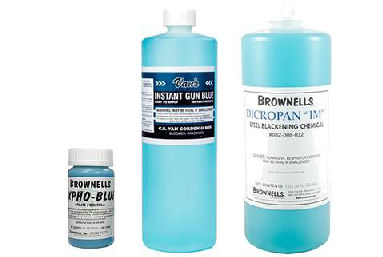
For
larger parts such as the magazine tube plug and barrel-band,
I polished and prepared the part as before, then heated the
part in a small toaster oven to 120-degrees Fahrenheit for
10 minutes. I poured some
Van’s Instant Gun Blue into a plastic bowl and
completely immersed the part. After the part turned black,
I removed it from the solution, wiped off the excess bluing,
then buffed with #000 steel wool.
For the
steel spacer plate, I polished and prepared the metal. I
plugged the chamber of the barrel with a rubber stopper, and
blued the plate with Brownells Dicropan IM
#082-008-032. This is a rust-bluing process and
requires much time and many applications, refer to my
article
Refinishing a .45 ACP
Conversion Cylinder with Brownells Dicropan IM®.
The other
change I made was to drill and tap the top of the front
barrel-band to accept an 8-40 x 0.130 set screw I purchased
from Brownells
#080-534-002. I drilled a corresponding indent in the
barrel, but was careful not to drill completely through the
barrel into the bore. This set screw sets below the bottom
of the front sight dovetail which still allows me to change
sights. It prevents the front barrel-band from rotating on
the barrel, which I accidentally discovered would happen
with the aluminum barrel-band.
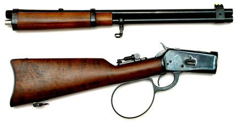
There’s
nothing like the look of blue steel and walnut. I’m glad I
didn’t try to refinish the rifle with any spray-on finishes,
and the new steel parts closely match the original factory
bluing. Next, I think I’ll try to convert a Marlin Guide
Gun in .45-70 to a takedown rifle. That should be an
interesting project.
[i]
Pete Dickey, “A Takedown Rifle,”
The NRA Gunsmithing Guide – Updated 1982, 273 -
276
|