Building the Ultimate .22 Trail Gun
by Roy Seifert
Click here to purchase a
CD with this and all Kitchen Table Gunsmith Articles.
Disclaimer:
This article is for entertainment only and is not to
be used in lieu of a qualified gunsmith.
Please defer all firearms work to a qualified
gunsmith. Any loads
mentioned in this article are my loads for my guns and have
been carefully worked up using established guidelines and
special tools. The
author assumes no responsibility or liability for use of
these loads, or use or misuse of this article.
Please note that I am not a professional gunsmith,
just a shooting enthusiast and hobbyist, as well as a
tinkerer. This
article explains work that I performed to my guns without
the assistance of a qualified gunsmith.
Some procedures described in this article require
special tools and cannot/should not be performed without
them.
Warning:
Disassembling and tinkering with your firearm may
void the warranty. I
claim no responsibility for use or misuse of this article.
Again, this article is for entertainment purposes
only!
Tools
and firearms are the trademark/service mark or registered trademark
of their respective manufacturers.
Introduction
I read an article in the December, 2013 issue of American
Rifleman about gun distributor Lipsey’s
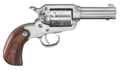
Guns commissioning a special production run of the Ruger®
new model Bearcat® called the Shopkeeper.
It was a new model Bearcat with a 3-inch barrel and
bird’s head grip in stainless steel.
I thought the idea of a small .22 revolver for camping,
trail, or tackle-box use was a great idea, but I didn’t want
to spend $650
to buy one, even though I’ve always wanted to own a Bearcat.
The author of the article also bemoaned the fact that
it didn’t come in .22 Winchester Magnum Rimfire (WMR) better
known as .22 magnum, with which I agreed.
I also didn’t like the fact that it came only with
fixed sights.
I
did some research on the Internet to see what else was out
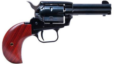
there for .22 magnum revolvers and I found that Heritage
Manufacturing Inc. produces a .22 caliber convertible
revolver called the Rough Rider for about 1/3 the price of the
Shopkeeper. The
Shopkeeper only comes with one cylinder chambered for .22
long-rifle (LR), but the Rough Rider comes with two cylinders;
one for .22 LR that will also chamber .22 short and .22 long,
and a second cylinder that will chamber .22 magnum.
Although this fine, very affordable revolver came with
a bird’s head grip and short barrel, I decided not to
purchase one. The
finish was blue, not stainless steel – not good if you’re
going to throw it in a tackle-box and use it around water; it
had fixed sights – I prefer adjustable sights; and it had a
Colt action. This
meant that with all chambers loaded and the hammer down, the
firing pin would rest on a loaded cylinder creating an unsafe
condition, so in reality you could only carry five shots, not
six. Although it
also had a hammer block, I just wouldn’t trust carrying the
gun with all six chambers loaded.
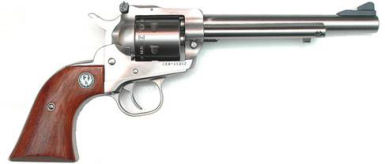
I
have two stainless steel Ruger new model Single-Six®
revolvers in my gun collection.
One is a “Liberty” gun manufactured in 1976 with the phrase, “Made in the
200th year of American
Liberty” engraved on the barrel.
The second one is just a regular model built sometime
in 2003. I had
originally purchased the second one to match the “Liberty” gun so I could teach a young person how to shoot cowboy
matches, but that never happened.
Since these guns have a transfer bar safety I can
safely carry them with all six chambers loaded.
These
guns both came with a 6 1/2-inch barrel and two cylinders; one
for .22 short, long, and long-rifle, and a second one for .22
magnum. I’ve
discovered over the years that when shooting .22 LR their
accuracy left something to be desired, but they shot .22
magnum very accurately. The
SAAMI bore diameter specification for .22 long rifle is 0.222,
but the bore diameter specification for .22 WMR is 0.224.
To prevent excessive pressure when shooting .22 magnum
the bore has to be a bit larger.
I slugged the bore on this project gun and it measured
0.223, which meant .22 LR bullets were a bit loose in the bore
so were not as accurate, but .22 magnum bullets fit tightly in
the bore which made them more accurate.
The
combination of stainless steel, adjustable sights, transfer
bar safety, and being able to shoot different types of .22
ammunition made this conversion a viable project.
The Shopkeeper is smaller and lighter than a
Single-Six, but I wanted the flexibility the Single-Six
offered.
Conversion
Plan
After reading the Shopkeeper article I decided to convert the
non-Liberty Single-Six into a trail gun by performing the
following:
- Set
back the rear sight
- Shorten
the ejector rod, ejector rod spring, and ejector rod
housing
- Cut
the barrel to 3 1/4-inches
- Shorten
the cylinder pin
- Install
a bird’s head grip frame
- Perform
an action job
These
changes would make the gun smaller, lighter, and easier to
carry, but obviously not as small nor as light as a Bearcat.
Also, the gun would be very usable for me, but could
also still be used by a “buckaroo” for cowboy action
shooting.
Setting
Back the Front Sight
I wanted to drill and tap the front sight and ejector rod
housing screw holes before I cut the barrel to ensure I had
enough barrel length to put into my milling vise.
The front sight is attached to the barrel with a single
6-40 screw, but I needed to make sure that when I marked the
barrel for the new screw hole, it was at the exact top of the
barrel.
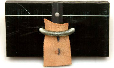
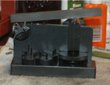
I
developed a tool out of a piece of polymer for marking the top
center of a round barrel.
The polymer block has a V-groove milled width-wise with
a hole in the center of the groove.
A U-bolt holds the block onto the barrel with a piece
of leather to protect the finish.
The white line you see on the bottom of the tool helps
me to align the hole properly along the length of the barrel.
I draw a line with a fine point marker down the side of
the barrel at the location of the sight screw and align the
white line with that mark.
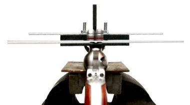
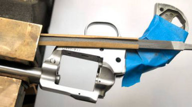
I
placed an aluminum bar across the polymer block and a second
bar across the flat top of the frame over the rear sight.
Notice that I’m holding the rear bar in place with
two lead bullets. I
rotated the block until the bars were parallel, inserted a
center punch into the hole in the block and struck it with a
mallet. The
resulting center punch was perfectly centered at the top of
the barrel.
The
proper hole size for a 6-40 tap is 0.113”.
I used a 3/32” (0.09375”) square end milling bit
and my hobby CNC mill to mill the hole.
I measured the depth of the original hole at 0.150”
deep, but the screw only protruded from the bottom of the
front sight by 0.115” so I decided to make the hole 0.140”
deep. I placed the
barrel in my milling vise, centered the bit over the center
punch mark, and milled the hole.
I used plenty of cutting oil so I wouldn’t break the
bit.
I
replaced the bit with a 6-40 bottom tap and used vice grips to
start the threads. I
lubricated the tap with cutting oil and after every 1/8 turn I
backed out the tap to cut the chips. Once the threads were
started I removed the gun from the vise and used a tap wrench
to finish tapping the hole.
When the tap bottomed out I removed it from the hole,
then cleaned off all oil and metal chips with brake parts
cleaner.
Shortening
the Ejector Rod Housing
This
was probably the most difficult part of the conversion process
because of the round lip at the end of the housing that fits
into the frame. But
thanks to my CNC mill it was actually fairly easy.
There were three things I had to take into account when
calculating how much to cut; one - the ejector rod, spring,
and housing had to be long enough to touch the bottom of the
empty case and push it out of the chamber, two - the cylinder
pin had to be short enough to accomplish the same thing, and
three - the cylinder pin had to also be short enough and the
ejector rod housing long enough so I could pull the pin and
remove the cylinder from the frame.
I
cut the ejector rod housing to 2 3/4-inches which included the
1/8” lip. No
matter how hard I try I just can’t make a straight cut by
hand, so I cut the housing 1/16” longer so I could square
off the face. The
inside of the housing measured exactly 1/4“ so I inserted a
0.250” milling bit into the housing, then chucked it in a
1/4” collet in my CNC mill so I could get it centered and
square in my milling vise.
I used a piece of leather to prevent marring the
housing.
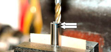
Once
the housing was secured in the milling vise I used the
0.250” square end bit to square off the end of the housing.
I milled down to the mark I made on the housing with a
blue marker. If
you look closely at the above photo you can see two blue marks
on the right side of the housing.
The top mark tells me where to stop squaring off the
end, and the bottom mark is the depth of the lip.

Next
I again used the 0.250” square end bit to mill the 0.306”
diameter lip 1/8” deep in the end.
After performing the milling the ejector rod housing
fit perfectly on the barrel and into the frame.
I could have performed this carefully with hand files
and achieved the same result, even though it would have taken
much longer.
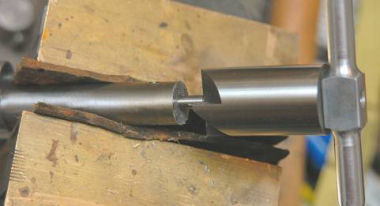
I
installed the housing on the barrel and used a center punch to
mark the location of the mounting screw hole.
This hole needed to be 0.125” in diameter by 0.140”
deep to accommodate the 8-36 mounting screw.
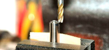
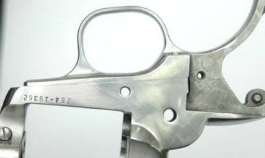
I
placed the barrel into the milling vise with the mark up and
centered a 0.125” bit on the mark.
I ran my CNC mill to plunge-mill the hole, then I used
an 8-36 bottom tap to tap the threads.
The result is shown in the above photo.
It looks kind of weird because as I mentioned before I
wanted to set back the front sight and cut and fit the ejector
rod housing before cutting and crowning the barrel.
Shortening
the Ejector Rod and Spring
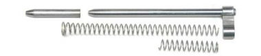
Now
that I have shortened the ejector rod housing, I needed to
also shorten the ejector rod and spring.
I installed the ejector rod into the housing without
the spring and installed the housing onto the gun.
The rod needed to be flush with the inside of the
frame. I marked
the rod and used my high-speed rotary tool with a cutoff wheel
to cut the rod, then I tapered and polished the end like the
original. I
measured the amount I cut from the rod and used wire cutters
to remove the same amount from the narrow end of the spring.
I had to cut 4 more coils off of the spring so when it
was completely compressed the rod would eject an empty case.
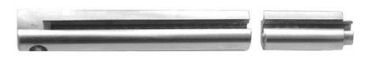
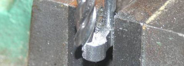
Cutting
the Cylinder Pin

Now
that I have a short ejector rod the cylinder pin was way too
long for the rod to even touch the head of the cartridge case
to eject it from the chamber, so I had to cut the pin, but I
couldn’t cut it flush with the frame, otherwise I wouldn’t
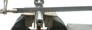
be able to remove it. The
factory pin had three grooves cut into it so I took my hack
saw and cut the pin at the middle groove.
I polished the cut end to remove the sharp edge and
teeth marks left from the saw.
Now the ejector rod ejects empty brass, but I
couldn’t pull the pin out of the frame far enough to remove
the cylinder. I
discovered this after I completed the gun!
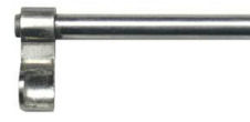
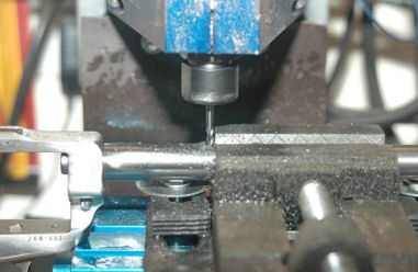
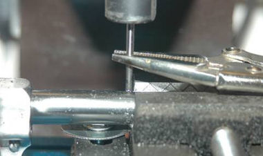
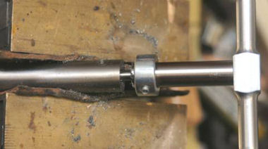
I
used a sharp scribe to mark where the cylinder pin touched the
ejector rod handle, then I used a long 1/4“ square end
milling bit to mill a notch in the handle as shown in the
above figures. I
used files and rubberized polishing bits to smooth out the
sharp edges and corners left from the milling process.
The
notch in the ejector rod handle allows the cylinder pin to
come back far enough so I can remove the cylinder, yet I left
the rear of the handle flat so my finger has a larger surface
to eject empty cases. The
Shopkeeper’s ejector rod handle is milled completely through
making a crescent handle, but I thought my solution was a
better compromise and unique.
Cutting
and Crowning the Barrel
This
turned out to be the easiest process of all because I had done
it before and had the correct tooling.
First I removed the front sight and ejector rod
housing. Then I
took a hacksaw and cut the barrel to 3 1/4“ plus 1/16”.
There’s nothing like the emotion of taking a hacksaw
to a perfectly good gun! As
mentioned before, I just can’t seem to make a straight cut
by hand so I cut the barrel 1/16” longer than necessary
which left me enough metal to square off the muzzle.
Next
I took my 90-degree facing cutter #080-586-
909 with a .22 pilot #080-943-211
that I purchased from Brownells and cut the muzzle square.
Next
I took a 1/2-inch 79-degree muzzle crown cutter #080-586-500
and cut a countersunk crown into the muzzle.
I placed a stop collar on the cutter to prevent the
cutter from chattering and cutting too deeply.
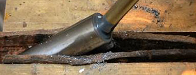
I
finished the process by lapping the muzzle with a .22 muzzle
lap. I put some
400-grit lapping compound on the end of the lap and while
running my drill at a slow speed less than 700 RPM pressed the
lap to the muzzle and rotated it in a circular motion.
This removed any burrs left over from the cutting and
crowning process. I
was explaining this process to one of my co-workers and he
wanted to know how I was going to remove the burrs left from
the cutting process. The
final lapping eliminates any nicks or burrs left from the
cutting, facing, and crowning process.
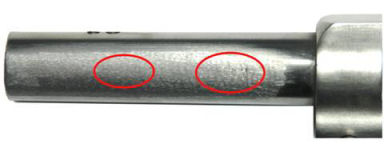
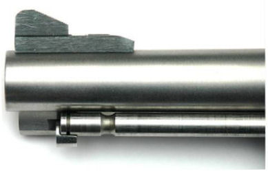
Cutting
the barrel cut into the factory engraving on the side of the
barrel which now detracted from the look of the gun.
I used a fine sanding drum on my high-speed rotary tool
to remove the engraving. You
can still see some of the engraving in the above photo.
I kept the drum moving up and down the length of the
barrel to prevent from leaving hollows and gouges in the
metal.
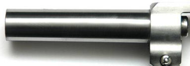
After
the engraving was removed I polished the barrel by
shoe-shining with 220-grit, then 400-grit wet/dry sand paper.
The above photo shows the result.
Fitting
the Bird’s Head Grip Frame
The stainless steel bird’s head grip frame I purchased from
MidwayUSA #821208
came oversized and rough cast so I had to fit it to my
existing frame, and do a lot of polishing.
This was the most time-consuming part of the entire
conversion process.
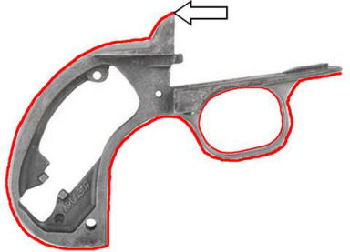
First
I used a fine sanding drum on my high-speed rotary tool and
polished all of the rough surfaces that would be final
polished. This was
the entire outside of the grip frame and inside the trigger
guard as shown in red in the above figure.
I again kept the drum moving along the length of the
metal to prevent leaving hollows or gouges.
Then I used the fine sanding drum to fit the curved
rear of the grip frame to the cylinder frame indicated by the
arrow. Finally I
polished all of the areas shown in red with 220-grit sand
paper. I made sure
to remove all sanding marks left from the sanding drum.
For the large areas I wrapped the sandpaper around a
piece of leather. For
small, hard to reach areas I wrapped the sandpaper around a
small file or piece of 1/4“ wooden dowel.
I finished polishing with 400-grit sand paper to get a
nice, smooth finish. For
the rounded areas like the front strap, back strap, inside and
outside of the trigger guard, I polished using a shoe-shine
motion. This was
to ensure I maintained the proper curves.
I
polished the sides of the trigger guard using 220-grit, then
400-grit sand paper wrapped around a narrow pillar file I
purchased from Brownells #191-400-760.
I wrapped the paper around the file to maintain the
flat surfaces of the trigger guard.
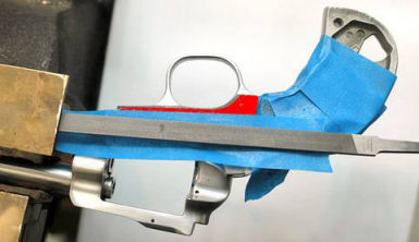
I
installed the grip frame onto the cylinder frame with the five
frame screws. I
taped both the frames to protect areas in case my file
slipped. I used
the narrow pillar file and carefully filed the edge of the
frame (shown in red in the above photo) until it just touched
the tape. This
meant I had about 0.003” left to be even with the cylinder
frame. I kept the
file flat and filed in one direction only.
I
wrapped a piece of 220-grit sand paper around the narrow
pillar file and finished blending the grip frame with the
cylinder frame. I
was careful not to touch the serial number.
Modifying or otherwise damaging the serial number is
against the law.
Once
the edge of the grip frame was even with the cylinder frame I
wrapped a piece of 400-grit wet/dry sand paper around the
narrow pillar file and finished polishing the frame.
I
performed the same process to side of the rounded rear of the
grip frame. I
again kept the file flat and filed in one direction only, then
finished with 220 and 400 grit sand paper.
The rounded rear of the frame side became flat, but I
gently rounded off the sharp corner with the file.
As you can see from the above photo the two edges mate
to the cylinder frame perfectly.
After
the grip frame was completely polished I bead-blasted both
frames, the loading gate, and ejector rod housing with glass
bead media to give them a soft, matt finish.
I could have given the gun a bright polish, but I
prefer the soft, matt finish for my trail gun.
Performing
an Action Job
When I purchased the “Liberty” Single-Six in 1977 the action was very smooth.
The Single-Six I purchased in 2003 was very rough!
My guess is with the increased demand for single action
revolvers Ruger could no longer spend the time to smooth up
the interior of the gun. I
spent a lot of time polishing the interior of the gun to get
it as smooth as the 1977 model, but I never performed a full
action job; all I did was polish the hammer and sear.
With the new bird’s head grip frame installed and the
original factory springs, the trigger pull measured 3
1/4–pounds, but was long with a lot of creep.
Usually
when I perform an action job on a Ruger single-action revolver
I replace the factory 23-pound hammer spring with a 19-pound
hammer spring, and replace the factory trigger return spring
with a reduced-power version.
Rim fire ammunition can be finicky so I decided to
leave the factory springs in place.
To
get a crisp trigger pull with no creep I first reduced the
length of the hammer engagement surface.
I installed the hammer in my Power Custom Series 2
stoning fixture I purchased from Brownells #713-270-014
using the universal adapter Brownells #713-271-000.
I used the original hammer pivot pin inserted groove
first into one of the holes in the adapter.
The pin was held in place by a set screw.
I made sure the set screw contacted the groove so as
not to raise a burr on the pivot surface of the pin. I marked
the front edge of the hammer notch with a blue marker and
adjusted the fixture until my stone was flat across the front
of the notch. The
notch in my hammer measured 0.022” so I took a 220 grit
stone and carefully reduced the depth of the notch to
0.014”.
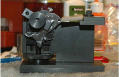
I
then rotated the hammer so I could polish the engagement
surface of the hammer notch as shown in the above photo.
I marked the surface with a blue marker and made sure
to adjust the fixture so I was polishing this surface
perfectly flat. I
used my hard Arkansas stone with a beveled edge to
final-polish the surface.
Next
I installed the trigger in my Power Custom Series 1 stoning
fixture Brownells #713-070-008
using the BH (Blackhawk) adapter Brownells #713-070-008.
I used a blue marker to mark the surface and adjusted
the fixture until I was polishing the surface perfectly flat
and square. I used
ceramic stones Brownells #080-721-621
to polish the sear. I
used the coarse ceramic stone to polish off all of the
grinding/machine tool marks, then final polished with the fine
ceramic stone. Ceramic
stones use water as the cutting agent, not oil.
I
applied a bit of Action Lube Plus available from Brownells #083-050-002
to the hammer and sear mating surfaces to ensure smooth
function and to prevent corrosion.
I also applied the Action Lube Plus to all surfaces
were metal touched metal.
All other areas I lubricated with Breakfree CLP.
I re-assembled the gun and tested the trigger.
It broke at exactly 2 1/2-pounds every time with no
creep.
Making
Custom Grips
I decided I didn’t like the polymer bird’s head grips, and
besides they didn’t fit correctly, so I decided to make my
own set out of Brazilian blood wood.
Refer to my article Making Custom
Handgun Grips for additional details.
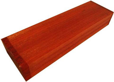
I
purchased a block of blood wood off of ebay.
The block measured 13 7/8” x 4 1/8” x 2 1/8”,
which meant I could cut 1/2“ slices off of the side to make
the scales I needed for my grips.
A scale is the block of material used to make a grip
panel.
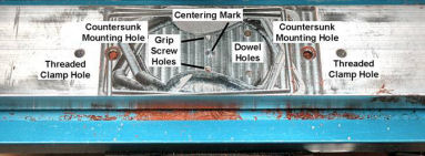
I
have a special jig that I made out of a 3” x 12” x 1”
piece of aluminum for making “plowshare” grips for Ruger
Vaqueros. This jig
holds the scale on my CNC mill for all of the milling
processes. I
discovered that the front edge, top edge, screw hole, and grip
panel dowel hole in the bird’s head grips were in the same
relationship as Vaquero plowshare grips so I had to make the
front and back of the grip match that relationship so I could
use the jig. There
are two grip screw holes, and two dowel holes in the jig to
hold a left and right grip panel in the proper orientation.
The centering mark helps me to center the jig in the X
(left-to-right) and Y (front-to-back) axes.
The two threaded clamp holes allow me to mount
adjustable clamps that hold the scale in place when milling
the screw and dowel holes.
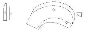
First
I used CorelDraw v12 to make the outline of the grips.
The three small pieces to the left and right of the
outline are the profiles of the top edge, front edge, and tip
of the bottom. Once
I exported these into BobCAD-CAM I rotated these pieces
90-degrees to start the 3D shape of the grip.
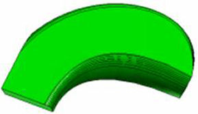
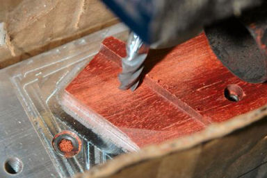
I
exported the CorelDraw shapes into BobCAD-CAM v20 which I used
to produce the 3D model and CNC code for my Max NC 10CL hobby
CNC mill.
The
process of producing the grips was pretty straight forward:
Step
1: Cut the scale
to 2 1/8 x 4 1/8 x 1/2
Step 2: Mill the
screw and dowel holes in the inside of the grip panel
Step 3: Mill the
ferrule hole in the outside of the grip panel
Step 4: Mill the
outline of the grip
Step 5: Mill the
3D shape of the grip (this process took 3-hours per panel)
Step 6: Hand fit
to the grip frame
Step 7: Sand and
finish
I
designed the pattern to be just a bit oversized so I could do
the final fitting to the grip frame by hand.
Once the grip panel was completed and properly fitted I
sanded it with 180-grit sand paper to remove any leftover tool
marks from the milling process, 220-grit sand paper, 400-grit
sand paper, then finished with 600-grit sand paper.
I applied three coats of Birchwood-Casey® Tru-Oil®
allowing the grip to dry for 6-hours between each coat.
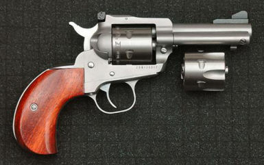
Summary
The Shopkeeper weighs in at 22 ounces as advertised, and the
Rough Rider at 33 ounces as advertised.
The factory Single-Six weighed in at 40 ounces but by
shortening the barrel, and changing to a bird’s head grip I
was able to remove 7 ounces so my trail gun now weighs in at
33 ounces, the same as the Rough Rider.
Both the Shopkeeper and Rough Rider didn’t meet all
of my requirements which are the reasons why I decided to
modify my Single-Six.
|