Making
Custom Handgun Grips
by Roy Seifert
Click here to purchase a CD with this
and all Kitchen Table Gunsmith Articles.
Disclaimer:
This article is for entertainment only and is not to
be used in lieu of a qualified gunsmith.
Please defer all firearms work to a qualified
gunsmith. Any loads
mentioned in this article are my loads for my guns and have
been carefully worked up using established guidelines and
special tools. The
author assumes no responsibility or liability for use of
these loads, or use or misuse of this article.
Please note that I am not a professional gunsmith,
just a shooting enthusiast and hobbyist, as well as a
tinkerer. This
article explains work that I performed to my guns without
the assistance of a qualified gunsmith.
Some procedures described in this article require
special tools and cannot/should not be performed without
them.
Warning:
Disassembling and tinkering with your firearm may
void the warranty. I
claim no responsibility for use or misuse of this article.
Again, this article is for entertainment purposes
only!
Tools
and firearms are the trademark/service mark or registered
trademark of their respective manufacturers.
Introduction
I’ve always had the desire to make my own custom handgun
grips. I decided
to start with 1911 grips because they’re somewhat flat and
fairly simple to make. Using
CorelDRAW®, my CAD/CAM
software BobCAD-CAM and
my MAXNC 10 CL
CNC hobby mill I felt I could design and create my own grips.
Jig
Before
beginning the design work on my grips I needed to build a jig
to hold the wood. I
purchased a piece of 3/4” x 3” x 12” aluminum from Online
Metals.com to use as the jig.
I milled six holes along the center length of the jig;
the two 0.201“ outside holes spaced 6.25“ apart I tapped
for 1/4-20 bolts. These
are used to hold the scale for drilling holes.
The next two holes are 0.258” drilled completely
through the metal with a 0.3752” countersink 1/4” below
the top. This
holds a 1/4-20 set screw for T fittings that hold the jig to
my mill table. Finally
the two inside 0.212“ holes spaced 3.074” apart I tapped
with a 1911 grip bushing tap.
I install a 1911 grip bushing in these holes to hold
the scale for final shaping by the mill.
After I
milled the holes I took a 3/16” square end bit and milled a
center mark on the jig. This
allows me to center the milling head each time I reinstall the
jig.
Designing
the Grips
I have the excellent book "The
U.S.
M1911/1911A1 Pistols: A
Shop Manual Volume 2" by Jerry Kuhnhausen.
Page 79 contains detailed measurements for 1911 grips
which I used for my design work.
I used
CorelDRAW® to do my initial design work.
First I scanned a pair of factory grips then traced the
outline. I used
the Kuhnhausen manual to adjust the dimensions and create the
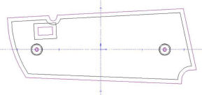
3-dimensional profiles. These
3-D profiles are located at either end of the grip outline.
The two red crosses at the bottom of each outline are
used to help me locate the bottom profile after I get it
rotated into the third (Z) dimension.
The small square below the left mounting hole of the
right grip is for the gap for the right part of an
ambidextrous thumb safety.
The line along the top of the left grip is for milling
a notch to allow for the plunger tube.
The two mounting holes are exactly 3.074” apart along
the center line. The
shape and 3-D profile of the grip is always with reference to
this center line.
Next I
exported each grip pattern as a drawing .dwg file, which I
then imported into the CAD/CAM program.
The CAD (computer aided design) part of the program
allows me to create a 3-D part.
I created all of the tool paths for the bushing and
screws holes, cutouts and notches, and the final outline.
Because I could use a 3/16” square end bit for all of
these cuts, the tool paths had to be offset by half of the
thickness of the bit, or 3/32”.
First I
created the tool paths for all of the holes.
I did the bottom holes first; the countersink for the
grip bushing, then the hole for the bushing itself.
At this time I also created the tool path for the
cutout on the right grip for the ambidextrous safety, and the
plunger tube notch on the left grip.
Next I created the tool paths for the top holes, which
are for the grip screw heads.
In the above figure, the purple lines are the tool
paths.
Now I
created the tool path for the outline of the grip.
Again, this tool path had to be offset by half of the
thickness of the 3/16” bit.
So far this
has been fairly easy because I’m working with a flat,
two-dimensional design. But
now I needed to create the three-dimensional shape of the
grip. I decided I
didn’t have to create a detailed 3-D shape with all the
notches and cutouts. Instead,
because I was going to cut the outline first I decided that I
only needed to create a general 3-D shape that followed the
contours of the grip.
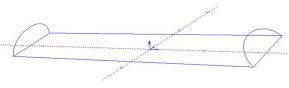
First I
rotated the top grip profile so it stood up straight; this is
now the top 3-D shape of the grip.
I rotated the bottom grip profile upright so it leaned
to the left by 45-degrees, then rotated it 12-degrees to match
the bottom outline. This
gave me the bottom bevel of the grip.
Using the software I connected the two 3-D profiles and
created a 3-D “skin” which was now the 3-D shape of the
grip without all of the notches and cutouts.
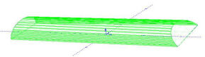
I created
the tool path for the 3-D shape based on a 5/16” ball end
bit. The tool path
starts in the center of the grip and cuts in a radial pattern
around the grip. The
3-D pattern is a little bit larger than necessary because I
designed the tool path to run off the edge of the grip and I
didn’t want the edge of the bit to remove any excess wood.
I also set the individual tool tracks very close
together so I could get a smooth grip with very few ripples,
which makes it easier to finish.
Scales
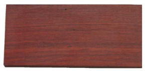
Creating a
grip begins with a blank piece of wood called a scale.
I found on the Internet some Brazilian blood wood that
makes beautiful, bright red grips.
This is more of a soft wood, like pine, rather than a
hardwood like walnut, but it has a very fine grain.
For 1911 grips I cut the blood wood into 3/8” x 2”
x 4 1/2” scales. I
take one side of each scale and sand it flat on my belt sander
using a fine-grit belt. This
is the inside of the grip that sets against the frame of the
gun.
Step
1: Milling the
Bottom Holes and Notches
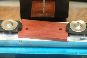
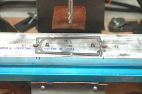
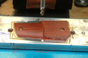
I position
the scale in the center of the jig and hold it in place with
brackets as shown in the photo.
I install the 3/16” square end bit and zero it to the
top of the wood. I
run the program that mills the grip bushing and bushing
countersink holes. If
this is going to be a right side grip, I also mill the
ambidextrous safety cutout.
If this is going to be a left side grip I mill the
plunger tube notch.
Step
2: Milling the Top
Holes
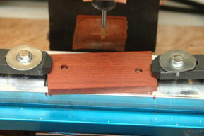
I remove
the grip and install the grip bushings onto the jig.
This keeps the scale properly aligned for all the other
operations. I turn
the scale over and install it onto the bushings and reinstall
the brackets. I
then zero the 3/16” bit to the top of the jig and mill the
two screw-head holes.
Step
3: Milling the
Outline
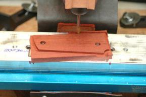
I remove
the brackets and install grip screws to hold the scale in
place. I now cut
the outline of the grip. When
this is completed I have a 3/8” thick grip that fits the
1911 frame, but it still needs to be milled to the proper
shape.
Step
4: Milling the
Final Shape
I install a
5/16” ball end bit, zero it to the top of the jig, and start
the final shaping program.
It takes about 90-minutes to mill the final shape of a
grip, but this is because I wanted the tool paths to be close
together so the result would be smooth.
Step
5: Engraving a
Design
Because I
have a CNC mill I can etch designs into the grip.
As with the grip itself, I first create the design
using CorelDRAW® then export the design to BobCAD-CAM.
With BobCAD-CAM I project the design along the curved
surface of the grip. This
now becomes the tool path for engraving the design.
I use a
0.02” ball end bit to engrave the design.
Because this bit is so small I remove 0.0005” with
each pass down to a total depth of 0.008”, and move it very
slowly.
Step
6: Final Finish
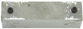
I mount a
completed grip onto a small piece of aluminum onto which I
have installed two grip bushings.
I hold this piece of aluminum in my hand so I can run
the grip over a piece of 150-grit sand paper to remove any
milling marks and make it smooth.
I final sand the grip first with 400-grit, then
600-grit sand paper.
Now that
the grip is finished I apply 3 coats of Birchwood
Casey® Tru-Oil® to all surfaces and inside all of the
holes. I allow
each coat to dry for 6 hours before applying another coat.
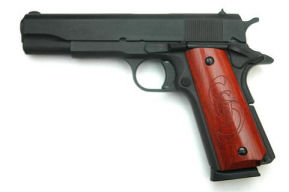
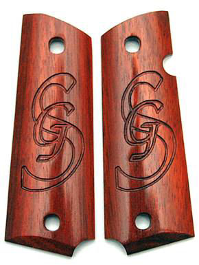
As you can
see from the photo, the results are spectacular.
These are a set of grips I made for my son engraved
with his initials.
|