Improving a Chinese Polytech M14S
by Roy
Seifert
Click here to purchase a zip file with this and
all Kitchen Table Gunsmith Articles.
Disclaimer: This
article is for entertainment only and is not to be used in lieu of a
qualified gunsmith. Please
defer all firearms work to a qualified gunsmith.
Any loads mentioned in this article are my loads for my
guns and have been carefully worked up using established guidelines and
special tools. The
author assumes no responsibility or liability for use of these loads,
or use or misuse of this article.
Please note that I am not a
professional gunsmith, just a shooting enthusiast and hobbyist, as well
as a tinkerer. This
article explains work that I performed to my guns without the
assistance of a qualified gunsmith.
Some procedures described in this
article require special tools and cannot/should not be performed
without them.
Warning: Disassembling
and tinkering with your firearm may void the warranty.
I claim no responsibility for use
or misuse of this article. Again,
this article is for entertainment purposes only!
Tools
and firearms are the trademark/service mark or registered trademark of
their respective manufacturers. Click on any
blue text to go to a
product/seller web site.
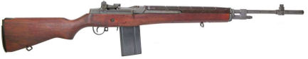
In 2001 I purchased a used Chinese Polytech M14S which is the Chinese copy
of the M1A. The M1A is the
semi-auto civilian version of the military M14.
When I fired this rifle, I was disappointed with the results.
In 2003 I decided to make some improvements to the look and accuracy
of this rifle.
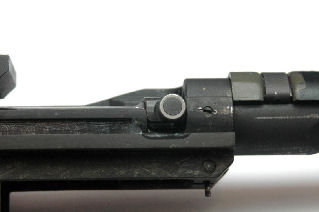
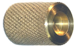
Replacing the Dummy Flash Hider
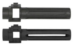
The
rifle came with a dummy flash hider; all the slots were solid.
I replaced the Chinese flash hider with a real flash hider that did not
have a bayonet lug. This was a
simple matter of loosening the castle nut set screw, unscrewing the castle nut,
placing castle nut in the new flash hider, then screwing the castle nut and new
flash hider onto the barrel. I
locked the castle nut in place with the castle nut set screw.
In spite of
Gunblue490’s
video, I purchased the castle nut wrench with the new flash hider.
Replacing and Camouflaging the Stock
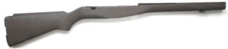
I
replaced the wood stock with a surplus fiberglass stock.
This removed some weight from the rifle.
Notice the stock has a cutout for the M14 selector switch, which my M1A
does not have.
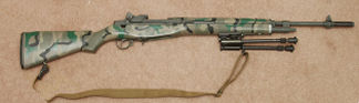
I
didn’t like the looks of the plain brown stock, so I used Brownells’
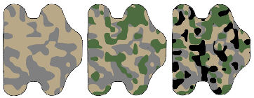
Aluma-Hyde paint to camouflage the stock and handguard.
I used matte black, flat dark earth, coyote brown, desert tan, and O. D.
green. I cut some stencils out of
masking tape, laid them on the stock and handguard, and spray painted through
the stencil. You can see the result
is an old-fashioned camo pattern.
I
added a bipod and web sling to the rifle.
I don’t remember where I purchased the bipod, or the manufacturer because
this was years ago, and there are no markings anywhere on the bipod.
Installing and Leveling a Scope
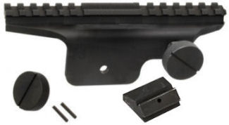
Along with the fiberglass stock I purchased a scope mount, but again, I don’t
remember from where I purchased it or the brand.
It looks suspiciously like a Springfield Armory scope mount, but I can’t
verify that. The mount came with a
replacement stripper clip guide with a hole drilled and tapped for the rear
screw. I replaced the stripper clip
guide on the rifle with the new guide and installed the mount.
This mount is tall enough that I can still use the open sights below the
mount.
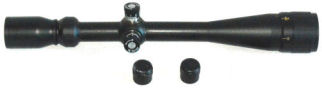
I
purchased a BSA 6-24 x 40 Mill Dot Scope and mounted it with scope rings onto
the scope mount. This scope has
parallax adjustment and turrets that can be zeroed.
The scope mount and scope added some significant weight to the rifle.
I looked online and apparently this scope is no longer available.
I found a used one on eBay for $70.00 just for reference.
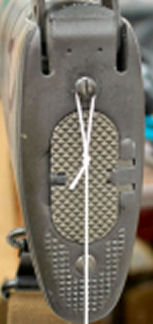
I
placed the rifle in a padded vise with the ocular lens facing the wall and hung
a plumb bob from the top butt plate mounting screw.
I rotated the rifle in the vise until the plumb bob string bisected the
bottom butt plate mounting screw.
I’m assuming that the action is parallel with the stock.
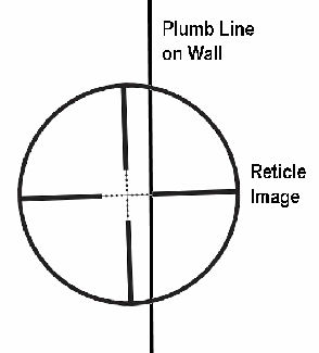
I
hung another plumb bob from a nail in the wall in my shop and shined a bright
flashlight through the objective lens of the scope so the reticle was projected
onto the wall next to the plumb bob string.
I rotated the scope so the projected vertical reticle was parallel to the
plumb bob string, then tightened the ring screws to 18 foot-pounds.
The scope is now level. In
the above figure, the scope needs to be rotated so the vertical reticle line is
parallel to the plumb line on the wall.
Even though I used a bright flashlight, I had to turn the lights off in
my shop to see the reticle image.
I’ve never had much luck using spirit levels to level a scope.
For me, the problem is getting the rifle level, and spirit levels don’t
seem to be accurate enough, or they are designed for bolt-action rifles.
This rifle has no level, flat spots on it.
The flashlight method always works, assuming the action is level with the
stock.
Fire-Lapping the Barrel
The accuracy of this rifle was very poor; I could barely hit a nine-inch paper
plate at 100 yards with the scope.
Maybe this was why the original owner sold it.
I figured the Chinese barrel was rough built and could probably be
improved by fire lapping. If I
messed up the barrel, I could always replace it.
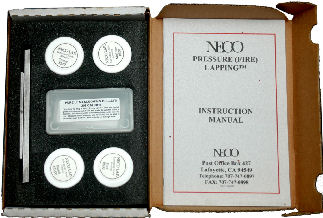
I
purchased a .308
NECO
fire-lapping kit, which included 4 grits of lapping compound, 220, 400, 800, and
1200, two steel plates to impregnate the bullets, and soft lead .308 bullets.
The soft bullets are for slugging the barrel.
I used copper-jacketed bullets which were more aggressive.
For
rifle barrels, NECO recommends firing five rounds of each grit, cleaning the
barrel, then slugging it to gauge the progress.
I prefer their other recommendation of shooting ten rounds of each grit
and cleaning the barrel after every five rounds.
It is important to thoroughly clean the rifle barrel after every five
shots to remove the powder residue and fouling.
Otherwise, I would be lapping the fouling and not the barrel.
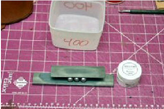
I
spread a thin layer of compound on the steel plate provided in the NECO kit and
rolled three bullets at a time between it and the other steel plate from the kit
thereby impregnating the bullets. I
wiped off the excess compound from each bullet and separated them by grit in
preparation for loading.
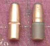
A
properly impregnated bullet has a gray ring around the bearing surface.
This surface provides the lapping action as the bullet travels down the
bore. I had some military surplus,
.308 Win brass and loaded each round with a light load of 5-grains of Red Dot,
which produced a low velocity load.
I normally destroy the cases after using them for fire lapping.
If I was to reload these cases, residual lapping compound could
contaminate the bullet, which would damage the barrel.
If I planned to fire lap more than one gun of the same caliber, I could
re-use the cases, but I would have to keep them separated by grit.
Ok, off to the range.
As mentioned before, I thoroughly cleaned the barrel after every five
shots with the rifle.
So,
what about the results, and just how effective is fire lapping for improving
accuracy? First, a fire lapped
barrel is much easier to clean.
Because pits and burrs are removed, there is nothing to hold fouling.
In most cases, a fire lapped barrel will come clean after only two or
three solvent-soaked patches. Fire
lapping also tapers the barrel from chamber throat to muzzle to make it more
accurate.
After fire lapping the barrel and cleaning up the muzzle with a brass muzzle
lap, I was consistently shooting 2-inch walnut husks at 100 yards.
On paper, I was printing sub minute-of-angle groups.
“Your results may vary”, as the disclaimers say, but I was quite stunned
by the results. I would not fire lap a
custom-made barrel because those are usually hand-lapped at the factory.
NECO recommends that the 220-grit lapping compound should not be used in
good quality factory barrels. I did
use the 220-grit on this Chinese M1A barrel because I could see it was very
rough inside.
The
downside of fire lapping is it increases the length of the chamber throat
thereby reducing the life of the barrel.
I don’t plan on shooting thousands of rounds through this rifle, and I am
very pleased with the results.
I
purchased this rifle in 2001 and made the above changes in 2003.
Now, some 20 years later, it’s time to make some additional improvements.
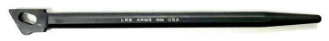
Replacing the Bolt
Some of the Chinese Polytech bolts are known to have improper heat treating
which can affect headspace. I never
had any problems with my Polytech bolt, but just to be sure, I purchased a
reclaimed USGI HRT bolt from
LRB Arms originally manufactured by Textile Machine Works for the Harrington
& Richardson Arms Co. (HRT) A
reclaimed M14 bolt is an original USGI bolt that was demilitarized by spot
welding the face and sometimes also the rear to make it unserviceable.
LRB Arms carefully removes the weld and machines the firing pin channel
and hole so the bolts can be made serviceable once again.
These bolts are carefully tested by LRB to be fully safe and functional.
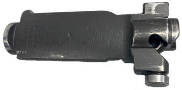
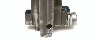
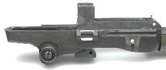
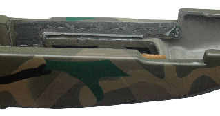
In
the above figure you can see the milled bolt face.
The bolt was stripped, but it did have the roller.
The rear of the bolt had not been touched; it was original.
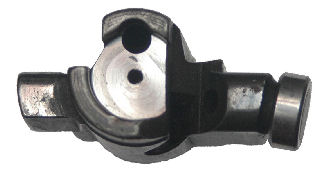
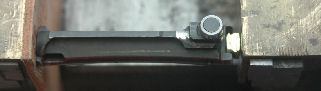
I
checked headspace with the new bolt using .308 Winchester gauges.
The bolt closed on the go gauge but would not close on the no go or field
gauge meaning the bolt and chamber were properly head spaced.
Notice in the above photo the bolt is not completely closed.
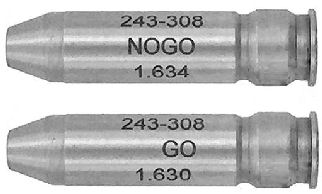
The gauge lengths are:
·
GO:
1.630 in.
·
NO-GO: 1.634 in.
·
FIELD: 1.638 in.
Verifying Bolt Lug Contact
Tonyben3 has a YouTube video on how to verify bolt lug contact and how to lap
the bolt lugs to the receiver.
https://www.youtube.com/watch?v=aMZjVJb0tRk&t=654s
It’s amazing what you can learn from the Internet.

First, I had to make a lapping tool.
I resized a military .308 Winchester case, cut it in half, and inserted a
spring. I didn’t use the hammer
spring like in the video; I used a spring from my stock of springs.
I filled the case neck with epoxy to prevent the spring from pushing
through.
I
marked the bolt lugs with a blue marker, inserted the unpopulated bolt into the
action, then closed the bolt on the lapping tool.
I used a 3/16” punch inserted into the extractor pivot hole to rotate the
bolt about 1/8”, then removed the bolt and checked the wear marks on the bolt
lugs. Both the HRT and Polytech
bolts were only contacting the right recoil lug.
Following Tonyben3’s video, I applied some 400-grit lapping compound to the
front edge of the receiver where the right recoil lug made contact.
I closed the bolt on the lapping tool and used the 3/16” punch to rotate
the bolt. After about 50 cycles of
turning the bolt, I removed the bolt from the receiver, cleaned off the lapping
compound, then measured headspace with the no-go gauge.
I continued the lap/measure cycle until the left recoil lug was just
touching the receiver. The bolt
still would not close on the no-go gauge.
I
removed the extractor, extractor spring and plunger, ejector and ejector spring
and firing pin from the Polytech bolt, but I had the worst time installing them
in the new bolt. I wrestled for
half a day, lost the extractor but had a spare, found it two days later, lost
the ejector but found it again!
There is a bolt assembly tool available, but I didn’t want to spend the money.

I
fabricated my own bolt assembly tool by cutting the head off a .30-36 case and
removing 1/4 of the case rim with a Dremel cutoff wheel.
Notice the nice clean cut in the above photo!
(I should have used my mill!)
I used this tool in my vise to keep the ejector compressed so I could
press the extractor in place. The
steps I followed to reassemble the new bolt were:
1.
Insert the ejector and spring in the bolt.
2.
Press the ejector against a finishing nail in a piece of wood so I could insert
a 3/16” punch in the extractor pivot hole.
3.
Pull the punch back through the bolt until I could insert the firing pin.
I kept my thumb over the ejector in case I pulled the pin out too far.
(Don’t ask how I learned this!)
4.
Insert the extractor plunger and spring.
5.
Place the assembly tool and bolt in a vise so the tool compresses the ejector.
Notice the firing pin end of the bolt is padded with leather.
6.
Remove the punch.
7.
Insert the extractor and press to seat it.
I had to use a small screwdriver to compress the extractor plunger so I
could press the extractor in place.
After assembling the HRT bolt, I lubricated the bolt with grease following
Tonyben3’s
YouTube video. I fabricated a
bolt roller lubricator on my lathe out of a piece of scrap brass rod and
lubricated the roller by filling the cavity in the lubricator about 1/2 full of
grease and pressing it on the bolt roller.
Shimming the Gas Cylinder
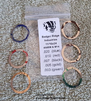
(Photo courtesy of Badger Ridge Industries)
I
found two different opinions on YouTube for shimming the gas cylinder.
Gunblue490 says to install shims so the front band and gas tube are barely
loose to accommodate the barrel heating up.
TonyBen3
says to install shims so the front band and gas tube are just barely tight.
A loose or sloppy gas tube can affect accuracy.
I purchased a M14/M1A Gas System shim pack from
Badger Ridge
Industries. These shims are
installed on the barrel behind the barrel band.
The gas system had to be completely removed from the rifle, which gave me
an opportunity to clean it. I tried
to install 0.013” of shims but I couldn’t turn the gas cylinder lock far enough.
The 0.007” shim left the band and gas cylinder barely loose, the 0.010”
shim left the band and gas cylinder barely tight.
I went with the 0.010” shim.
Glass Bedding the Stock
I followed Gunblue490’s YouTube video titled
How to Glass
Bed an M1A or Garand ~ In Just 25 Minutes!
It took me much longer than 25 minutes!
I used JB Weld which takes 24 hours to cure, so I had to wait between
each application of epoxy.
wel in the recoil lug recesses and filled the gaps with JB
Weld. I used
Minwax Paste Finishing Wax as my release agent.
I couldn’t get the dowel flush with the recoil lugs, so I recessed it
from the outside edge and filled the gap with epoxy.
I used waxed flat craft sticks to make the epoxy flush and held the
sticks in place with a clamp. After
the epoxy cured, I trimmed it with an Exacto knife.
I filled the connector lock holes and bolt stop gap with plumber’s putty.
I
used a Dremel tool and 1/8” round burr to cut channels in the fiberglass stock
as seen in the video. I thoroughly
waxed the receiver and inside of the stock where I didn’t want epoxy to adhere.
I
placed JB Weld on the areas of the stock where the edges of the receiver and
recoil lugs touched and held the action down with electrical tape as shown in
the video. I turned the rifle over
and removed the excess epoxy that was squeezed out.
I used about 1/3 of each tube, but really didn’t need that much.
Still, it’s better to have some left over than to not have enough.
I allowed the epoxy to cure for two days before removing the barreled
receiver from the stock.
After I removed the action from the stock, I removed any excess epoxy.
You can clearly see a ledge in the above photo.
JB Weld is thin and will run if not allowed to cure for 20-minutes or so before
applying. This was my second attempt at bedding and there are
things I would do differently next time, e.g. completely remove that ledge of
epoxy from underneath the action. I
used a small grinding bit and my Dremel tool to remove the ledge.
I cleaned off the wax from the receiver with alcohol and a toothbrush,
removed the plumber’s putty, then lubricated and reassembled the rifle.
The action is nice and tight in the stock which should improve accuracy.
Checking for Bolt Roller Contact on the Receiver
TonyBen3 has another YouTube video on how to check and correct for bolt roller
receiver contact.
https://www.youtube.com/watch?v=wArG8l7mjk8&t=44s
As it turned out, the Chinese Polytech receiver was undercut below the
bolt roller so the roller wouldn’t impact the receiver.
So, this is one problem this rifle should never encounter.
Adding a M1907 Sling
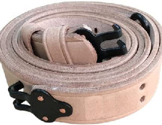
I
purchased a M1907 sling from
OpticsPlanet.com. I chose the
unstained, natural version so I could oil it myself like soldiers did when the
original slings were first issued.
I have made M1907 slings in the past, refer to my article
Making an M1907-Style
Rifle Sling but it was cheaper just to buy one.
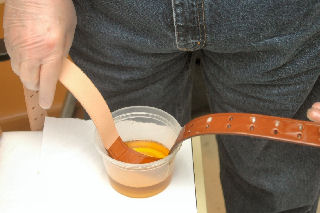
poured
neatsfoot oil into a plastic container and ran the two strips and keepers
through the oil. I wiped off the
excess oil and hung them up to dry.
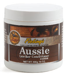
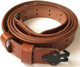
After the leather dried I rubbed in
Fiebing’s Aussie Leather Conditioner I purchased from the
Tandy Leather Company.
This contains beeswax which will help to protect the leather.
I
removed the bipod and installed the sling following the instructions in my
article Making an
M1907-Style Rifle Sling. I
like the looks of the M1907 sling on my military rifles.
This sling also serves to steady the rifle in the prone, sitting, and
kneeling shooting positions.
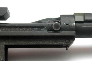
Installing a National Match Operating Rod Spring Guide
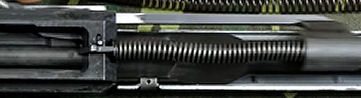
The
US GI spring guide can allow the op rod spring to buckle which can cause
inaccuracy. In the photo above you
can see the op rod spring is starting to buckle under recoil.
I
purchased a national match operating rod spring guide from
LRB Arms.
The national match op rod spring guide allows the spring to contract
without buckling which may improve accuracy.
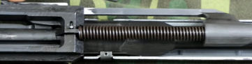
I
replaced the standard op rod spring guide with the national match op rod spring
guide. Now the spring does not
buckle when compressed.
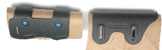
Installing a Cheek Riser
I needed to install a cheek riser so my eye would reach the scope but still get
a good cheek weld on the rifle. The
strap-on soft cheek risers were too flimsy, and I didn’t want to drill holes in
my stock to attach a hard cheek riser.
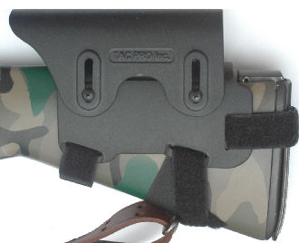
I
found a company on the Internet called
Tac
Pro and purchased their adjustable M14/M1A cheek rest.
The Kydex base straps onto the buttstock, and the adjustable cheek riser
attaches to the base. The base has
rubber inserts to prevent it from moving.
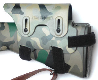
The
three straps make the installation rock solid.
I didn’t like the fact that the rear strap fit over the butt plate.
I would not be able to fold out that section, nor access the storage in
the butt stock without loosening the strap.
I tried putting the strap under the fold-out section, but the three
layers of Velcro wouldn’t allow the fold-out section to close.
I thought about filing a cutout in the fiberglass stock under the butt
plate but decided to leave it alone.
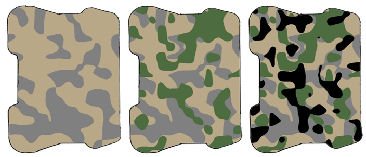
I
wanted to camouflage the cheek riser like I did the stock.
Many years ago, I found a camouflage pattern generator by
Van Der Lee that is a
plug-in for my Paint Shop Pro program.
This plug-in allows me to create various camouflage patterns.
Once I find a pattern I like, I create stencils by printing just the
color and cutting out that color.
I
traced the outline of the top and bottom parts of the cheek rest and scanned
them into my computer. I used the
camouflage plug-in to create a camouflage pattern for each part.
I printed out each individual color, then cut out those colors from the
pattern.
I
laid strips of blue painter’s tape onto a sheet of wax paper, then traced the
holes from the pattern onto the painter’s tape.
I cut out the holes from the painter’s tape, removed the wax paper, then
laid the adhesive stencil onto the part.
I
taped brown paper on the inside of each part so I wouldn’t get paint on the
rubber inserts. I put blue
painter’s tape on the screws and installed them so paint wouldn’t get in the
threads or in the screw heads.
I
sprayed both parts with gray self-etching primer and allowed it to dry for 12
hours. This is the base color for
the camouflage pattern. I applied
each adhesive stencil for the color I wanted to paint.
After the paint dried, I removed the stencil, applied the adhesive
stencil for the next color, then painted that color.
Again, after the paint dried, I removed the second stencil, and performed
the same process for the third color.
After the third color dried, I sprayed the part with matt clear coat.
After the clear coat dried, I removed the brown paper from inside,
removed the protective tape from the screw heads, reassembled the cheek rest,
and installed it onto the stock.
The camouflage pattern matches the stock, and I can now get a firm cheek hold
when using the scope. If I want to
use the regular sights, I adjust the cheek riser to its lowest setting.
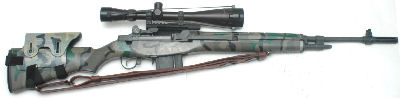
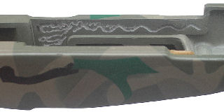
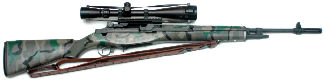
The
above photo shows the completed M14S/M1A.
Since I’ve made changes to the stock, op rod spring guide, and gas block,
I expect the rifle will shoot differently than before the changes; hopefully it
will shoot better.
Bore Sighting
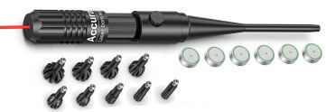
I
have a Bushnell universal laser bore sighter that fits into the end of the
muzzle. I never liked the lasers
that fit into the chamber because I could never get a clean dot; there was too
much interference from reflections in the bore.
The photo above shows the
EZshoot bore sighter available from Amazon.com which is similar to the
Bushnell model. This is an
inexpensive, valuable tool if you plan to mount a scope or change iron sights.
Bore sighting should get your first shots on paper, then you can fine
adjust your scope/sights with actual shots at the range.
I bore sight in my house at 24-feet (8-yards).
Because I’m inside, I don’t have to contend with wind, bright sunlight,
or long distances. (I just have to
contend with cats that want to chase the laser dot!)
This rifle will not allow me to bore sight using the traditional method
of sighting through the barrel to a target, then adjusting the sights to match.
I can’t look through the barrel of the M1A because the receiver is in the
way.
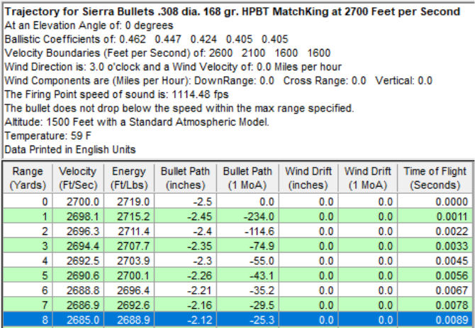
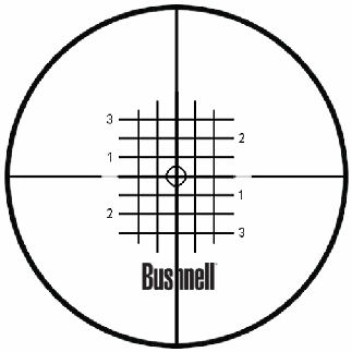
I
used Sierra Bullets Infinity Suite v6 to calculate the trajectory of my favorite
.308 load with Sierra 168-grain hollow-point boat-tail Match King bullets at
2,700 FPS. Sighted-in for 100-yards
the bullet would be 2.12-inches low at 8-yards.
So, this means I need to adjust my scope so the laser dot is 2.12-inches
below the scope’s crosshairs.
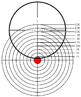
Standing 24-feet in front of my target, I adjusted the scope until I saw the
image as depicted in the drawing above.
Again, this should get me on paper at 100-yards.
The figure above is a drawn representation of the actual image.
Alternative Bore Sight Method
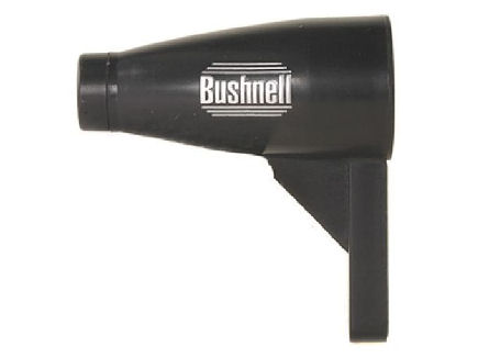
I
purchased a Bushnell magnetic bore sighter from
MidwayUSA
that attaches to the muzzle with a magnet.
This allows me to adjust the height of the bore sight to match the height
of the scope above the muzzle.
First, I made sure the horizontal and vertical adjustments on the scope were
both in the middle of travel. I
attached the magnetic bore sight to the muzzle of the rifle and adjusted the
height to match the height of the scope.
I rotated the bore sight until the horizontal and vertical lines were
parallel with the horizontal and vertical reticle lines on the scope.
I
adjusted the windage and elevation knobs on the scope until they were centered
on the bore sight image. Then I
dialed 17 clicks up which relates to 2 1/8-inches.
Each click of this scope is 1/8 MOA, or 1/8-inch at 100 yards.
Since I needed to be 2 1/8 inches high this should get me on paper at
100-yards.
Range Time
I have three loads I want to try:
1.
Sierra 168-grain hollow point boat tail Match King handload @ 2,700 FPS
2.
Lake City 1968 150-grain boat tail FMJ surplus
3.
Winchester 147-grain boat tail FMJ handload @ 2,700 FPS
Many years ago, I purchased 1,000 Winchester 147-grain boat tail FMJ bullets.
I use these to load .30-06 for my Springfield ’03-A3 and my M1 Garand.
I want to find an accurate load for the M1A .308 Winchester using those
bullets as well. At the time of
this writing, Sierra 168-grain Match King hollow point boat tail bullets were
costing anywhere between $0.47 to $0.55 per bullet!
I found these to be very accurate in this rifle, and if I can’t get the
147-grain bullets to work, I’ll purchase more of the Sierra Match King bullets.
As mentioned before, I don’t plan on shooting thousands of rounds through
this rifle, just occasional trips to the range to shoot targets.
I'll publish another article with the results.
|