Improving Two Pietta
Remington 1858 New Army Revolvers – Part 2
by Roy
Seifert
Click here to purchase a zip file with this and
all Kitchen Table Gunsmith Articles.
Disclaimer: This
article is for entertainment only and is not to be used in lieu of a
qualified gunsmith. Please
defer all firearms work to a qualified gunsmith.
Any loads mentioned in this article are my loads for my
guns and have been carefully worked up using established guidelines and
special tools. The
author assumes no responsibility or liability for use of these loads,
or use or misuse of this article.
Please note that I am not a
professional gunsmith, just a shooting enthusiast and hobbyist, as well
as a tinkerer. This
article explains work that I performed to my guns without the
assistance of a qualified gunsmith.
Some procedures described in this
article require special tools and cannot/should not be performed
without them.
Warning: Disassembling
and tinkering with your firearm may void the warranty.
I claim no responsibility for use
or misuse of this article. Again,
this article is for entertainment purposes only!
Tools
and firearms are the trademark/service mark or registered trademark of
their respective manufacturers. Click on any
blue text to go to a
product/seller web site.
Introduction
It’s been over six years since I first worked on my two Remington 1858 New
Model Army Sheriff’s Model revolvers by Pietta (refer to my article
Improving Two Pietta Remington 1858
New Army Revolvers).
In this article I will continue improving these revolvers based on
videos I found on YouTube. Here
is my improvement plan:
·
Modify the cylinder base pin for reliability
·
Replace the spot-welded front sight with a dovetail
front sight
·
Replace the spot-welded/epoxied loading lever latch
with a dovetail latch
Modifying the Cylinder Base Pin for Reliability
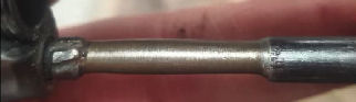
I
recently saw a YouTube video by Everything Black Powder titled
“The Ultimate Remington Upgrade” where Jake modified the cylinder base
pin to eliminate fouling. The
photo above shows the modified cylinder base pin from Jake (a different
Jake) Pearce’s revolver taken from Everything Black Powder’s video.
With this modified base pin, he fired 12 full cylinders (72 shots)
with no lube and had no binding of the cylinder or action.
The only reason he stopped was because he ran out of lead round
balls. He used a Dremel tool and
files to modify his base pin, but I have a lathe and CNC mill which should
make the modifications easier.
If you
notice in the above photo, the end of the base pin close to the barrel has been
cut with angled grooves to cut and funnel fouling away from the frame and inside
the center of the cylinder. The
center of the base pin has been narrowed so fouling does not bind the cylinder.
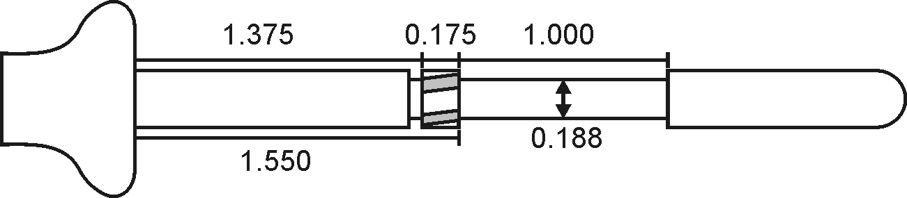
The
section with the grooves measures 0.175-inches wide, and the narrowed diameter
part measures 1.000 x 0.188-inches.
I calculated this by using the Figure 1 photo, importing it into CorelDraw V12
and resizing it so the diameter of the base pin in the photo measured
0.272-inches, then measured the other parts in the photo.
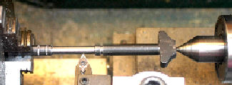
I
purchased two spare cylinder base pins in case I made a mistake.
Based on the video and this article there may be a run on spare base
pins! I chucked a base pin in my
lathe close to the fat end and used a small center drill to make an indentation
in the end for a live center. I
pulled the base pin out and chucked it on the round end.
I used a live center in the indentation to prevent the pin from wobbling
while turning.
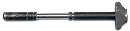
I
turned down the base pin to the measurements above.
I used a 60o tool so the edges would be tapered.
I used the same tool to cut the groove on the opposite side of the
cutting face to a depth of 0.040-inches.
You can still see the grooves I originally cut back in 2020.

I
wanted to use the rotary Z-axis and my CNC mill to cut the cutting face on my
modified base pin. But first I had
to do some calculations to figure out how much to rotate the Z-axis for each
cut.
|
|
|
Z-axis Setting
|
Degrees
|
|
1.
Diameter
|
0.272”
|
|
|
|
2.
Circumference
|
0.855”
|
2.73
|
68.4 o
|
|
3.
Cutting face tooth width
|
0.070”
|
4.97
|
124.2 o
|
|
4.
Milling bit width
|
0.063”
|
7.20
|
180.0 o
|
|
5.
Rotation distance
|
0.133”
|
9.43
|
235.8 o
|
|
6.
% of circumference
|
0.155
|
11.67
|
291.6 o
|
|
7.
Degrees
|
55.82o
|
|
|
|
8.
Z-axis
|
2.23
|
|
|
Rotary Z-Axis Settings
The
above table shows my calculations.
Here is the math:
1.
The
diameter of the base pin is 0.272”.
2.
The
circumference is 0.855”. (π * diameter, 3.141 * 0.272)
3.
The
cutting face tooth width is 0.070” (see Figure 5 above).
4.
The
milling bit width is 1/16, 0.0625” (see Figure 5 above).
5.
The
pin has to be rotated 0.133-inches between cuts (tooth width 0.070 plus milling
bit width 0.0625 = 0.133).
6.
0.133
is 15.5% of the circumference.
(0.133/0.855 = 0.155 = 15.5%)
7.
The
pin has to be rotated 55.82-degrees between each cut. (360o * 0.155 =
55.82o)
8.
For
every degree of movement, I need to enter a G-code command of A0.04.
To rotate 55.82-degrees I need a G-code of A2.23.
The
rotary Z-axis works by position, not by degrees.
I built Table 1 by starting with a G-code of A7.2 to turn the base pin by
180o then subtracted 2.23 twice and added 2.23 twice.
If I start with the flat part of the base pin up so I can level it in my
chuck, my first G-code command is G00A2.73.
This rotates the pin to position 68.4-degrees, then I make the 10-degree
diagonal cut. Next, I move the
Z-axis to 124.2-degrees (G00A4.97) and make another 10-degree diagonal cut, and
so on.
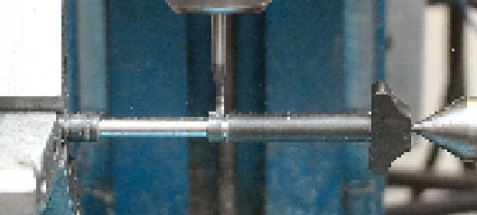
I
chucked the base pin in the rotary Z-axis of my Max NC 10 CL CNC mill with the
flat side up and supported the end with a dead center.
I used a 1/16 square-end bit to mill 10-degree diagonal grooves in the
narrow section similar to the photo in the video.
I milled 0.0025” at a time so I wouldn’t break the small bit.
I milled to a depth of 0.042” which matched the depth of the milled
center section.
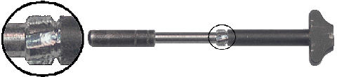
After
all the milling was complete I applied Brownell’s
Oxpho-Blue to the exposed metal.
Now the base pin can be reinstalled in the revolver.
Replacing the Spot-Welded/Epoxied Loading Lever Latch
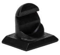
The
loading lever latch was spot-welded in place.
I had removed the latch back in 2020 to turn grooves in the base pin,
then used JB Weld to reinstall the latch.
The latch came free of the epoxy with just a light tap of a mallet.
To ease removal of the base pin, I wanted to replace the latch with a
dovetail version. Uberti makes their
loading lever latch with a dovetail.
I purchased two Uberti loading lever latches from
Gunpartscorp.com
but these can be found cheaper elsewhere.
The
latch's dovetail is 0.347” wide at the bottom, the base is 0.060” thick.
The angle is 74 degrees, and the cutter used is 1/4 inch x 74 degrees,
available from Brownells, part #
080-621-250. I found a 74-degree
carbide dovetail cutter on eBay
for a lot cheaper.
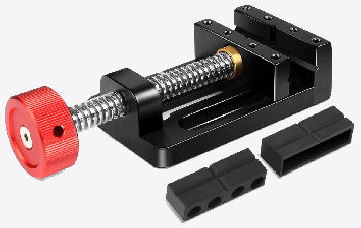
I
purchased a mini vise from
Amazon to hold the barrel of the revolvers.
This vise came with pads for the jaws so I don’t mar the finish on the
barrel.
I
chucked the revolver upside-down in the milling vise for my CNC mill and leveled
it. I centered the mill over the
mounting hole left from the latch.
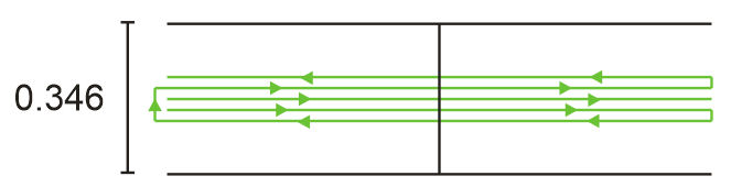
I took
some measurements to tell me how to set the tool paths for the dovetail cutter.
The black lines in the above diagram represent the final dimensions of
the dovetail cut. The edges of the
cut are 0.346” apart; 0.001” less than the actual width for a tight fit.
The green lines represent the tool paths.
The center green line is the tool path for initial cut to mill out the
center of the dovetail cut. The
other green lines are the tool path for the edges of the dovetail cut.
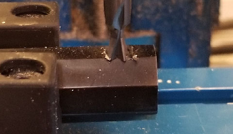
First,
I milled the center of the dovetail cut using the dovetail cutter.
I cut 0.005” each pass until I cut to a depth of 0.060”.
After I milled the center of the dovetail cut, I kept the cutter at the
0.060” depth and milled the edges.
Although the cutter is carbide, I didn’t want to overload it so I took small
cuts. If you follow the arrows in
the above diagram, you can see the toolpath.
Replacing the Spot-Welded Front Sight
The
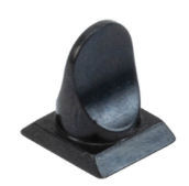
front sight on these revolvers was also spot-welded in the barrel preventing
them from being adjustable. The
Uberti model front sights are dovetailed in the barrel making them adjustable
for windage. I purchased two Uberti
front sights also from
Gunpartscorp.com. A tap with a
steel punch broke the sight free from the spot weld.
The
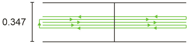
sight's dovetail is 0.348” wide at the bottom so I made the cut 0.347”, the base
is 0.060” thick. The angle is 74
degrees, and the dovetail cutter is the same I used for the front sight.
As
with the latch I first used the dovetail cutter to mill out the center of the
cut. I again milled 0.0025” deep
each pass and moved the bit slowly so I wouldn’t damage the bit.
Because the bit was carbide I didn’t worry too much about damaging it.
I kept
the dovetail bit at the 0.060” depth and milled the edges of the dovetail.
After milling I cold-blued the exposed metal, then installed the front
sight. It fit nice and tightly in
the dovetail.
Now
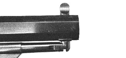
both of my Pietta Remington 1858 New Model Army Sheriff’s Models have a
dovetailed front sight and loading lever latch.
The front sight is windage adjustable and the loading lever latch can be
removed if I need to remove the cylinder base pin.
|