|
|
Strain
Gauges for Chamber Pressure Measurements
by Roy Seifert
Click here to purchase a
CD with this and all Kitchen Table Gunsmith Articles.
Disclaimer:
This article is for entertainment only and is not to
be used in lieu of a qualified gunsmith.
Please defer all firearms work to a qualified
gunsmith. Any loads
mentioned in this article are my loads for my guns and have
been carefully worked up using established guidelines and
special tools. The
author assumes no responsibility or liability for use of
these loads, or use or misuse of this article.
Please note that I am not a professional gunsmith,
just a shooting enthusiast and hobbyist, as well as a
tinkerer. This
article explains work that I performed to my guns without
the assistance of a qualified gunsmith.
Some procedures described in this article require
special tools and cannot/should not be performed without
them.
Warning:
Disassembling and tinkering with your firearm may
void the warranty. I
claim no responsibility for use or misuse of this article.
Again, this article is for entertainment purposes
only!
Tools
and firearms are the trademark/service mark or registered trademark
of their respective manufacturers.
Introduction
A few years ago, I purchased
the excellent Pressure
Trace device available from Recreational
Software, Inc.
for measuring chamber
pressure. This
device uses a strain gauge glued to a rifle barrel to
measure the pressure.
The strain gauge is located over the mid-point of the
chamber and is connected to
the battery-operated device.
The device is connected to the serial or USB port of
a laptop running graphing software.
The strain gauge actually measures how much the
barrel stretches, which is converted to a pressure value.
I purchased this device to accurately determine when
my reloads were reaching maximum pressure.
Relying on visible excessive pressure indicators like
cratered or backed-out primers, case head expansion, or
separated case heads, is somewhat inaccurate and usually
means the loads are already beyond maximum pressure.
I have also used chamber pressure measurements to
compare how different powders, or other reloading
components, affect pressure and velocity in a given load.
A strain
gauge is a resistive grid laid on some type of substrate
material. You
install the gauge onto the rifle barrel with special
super-glue or epoxy. Regular
store-bought super glue cannot be used with strain gauges as
this will cause problems.
When you fire a shot, the steel stretches a small
amount, which changes the resistance of the strain gauge.
This change in resistance causes a minute change in
voltage, which is amplified by the device and sent to the PC
where it is graphed and stored.
The
manufacturer of this device sells additional strain gauges
with leads and connector for about $30 each by the time you
pay shipping. You
have to purchase a minimum quantity of three, which is about
$90. I thought I
could beat that price to attach a strain gauge to my other
rifles, so I began searching the Internet for materials.
Refer to the end of this article for a list of parts
and sources.
Strain
Gauge
The
manufacturer of the device states that you need a strain gauge
of 350 ohms resistance capable of conducting up to 5 volts.
The gauge they use is CEA-06-125UN-350
available from the Vishay
Precision Group. I
looked them up on the Internet and found they have offices in
my own state. I
sent a request for a quote, and they responded with a price of
$6.40 apiece with a minimum quantity of 10.
So, with tax and shipping, the price came to $7.50
each. I
also asked for a quote for the same gauge with leads already
attached, and the price doubled, so I decided I could solder
my own leads to the gauge.
(I believe the device manufacturer purchases the gauges
with the leads already attached, which directly affects their
cost.)
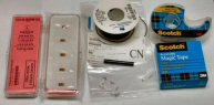
Connector
& Wire
The device manufacturer also sells just the leads and
connectors so you can attach them yourself to your own strain
gauge. However,
each connector assembly costs about $5.00, which again I
thought I could beat by purchasing my own wire and connectors.
Once again, thanks to the Internet, I stumbled upon Mouser
Electronics. After
carefully measuring the original connectors, I found that
Mouser carried the Molex series 51047 connectors I was looking
for. I purchased
10 receptacles and the male pins for them, which came to $0.55
per connector. I
also ordered 100 feet of 28-gauge wire for about $22.00.
Using only about 3” per gauge, the price of the wire
was $0.06.
In
addition, I had to purchase some special adhesives and
heat-shrink tubing, so all together, including tax and
shipping, the cost was at, or a few cents under $9.00 each.
That represented a $21.00 savings, which was definitely
worth the little bit of elbow-grease, wire, and solder to make
my own strain gauge assembly.
(If you think $90.00 was too expensive, remember that
this allowed me to attach a strain gauge to 10 of my or my
friends’ guns, instead of to only three guns.)
Connector
Assembly
First,
I assembled the connector.
I cut two pieces of 28-gauge wire about 1 1/2 inches
long. I stripped
1/4 inch off each piece and tinned the exposed end.
I placed the tinned end into one of the male pins for
the connector, crimped the end, and then soldered the wire.
I had to be sure the crimped ends were below the level
of the pin’s locking tab, and that I didn’t leave a large
solder ball, otherwise the pin would not fit into the
connector. If
there were any high spots, I used a Dremel tool with a cutoff
wheel to carefully grind them away.
After soldering a pin to each lead, I inserted them
into the connector, making sure they clicked firmly into
place.
I
discovered through trial and error (and wasting a couple of
connectors) that the soldered wires became brittle and broke
where I soldered them to the connector pins.
To fix this problem, I put a drop of Armstrong A-12
epoxy on the back of the connector making sure I covered the
wires and the connector. Armstrong
A-12 is an electrically insulated epoxy; I tried using J-B
Weld, but it has iron powder in it so it is not electrically
insulated. After
the epoxy dried, I protected the joint with a piece of
heat-shrink tubing. The
epoxy and heat-shrink tubing act as strain relief to prevent
the wires from breaking off the connector pins through normal
handling. I
purchased the heat-shrink tubing from Radio
Shack, and the
Armstrong A-12 epoxy from Small Parts, Inc (www.smallparts.com).
The epoxy cost over $28.00, but for this application,
you only need a couple of small drops, so it should last a
very long time.
Strain
Gauge Assembly
The
Vishay web site has complete instructions for attaching lead
wires to the strain gauge.
I followed their instructions using the 28-gauge wire I
already attached to the connector assembly.
First I degreased a flat piece of steel I use for
impregnating bullets with fire-lapping compound.
Then I degreased a pair of tweezers, picked up the
strain gauge being careful not to touch the grid, and laid it
on the steel. I
covered it with a piece of Scotch
811 removable tape that covered approx 1/3 of the solder tabs.
I couldn’t use normal tape; otherwise I could damage
the gauge. I
purchased the tape at my local office supply store.
For
the soldering process, I made sure the soldering iron tip was
perfectly clean and tinned properly.
I used a variable temperature soldering iron and
adjusted it for the lowest setting that would melt the solder.
I carefully stripped about 1/4 inch of insulation from
the ends of the 28-gauge wire on the connector assembly and
tinned the exposed wire. I
cut the tinned lead leaving only about 0.1” of tinned wire,
just enough to cover the exposed solder tab on the gauge.
I put a small drop of solder on the tinned end and laid
it on one of the strain gauge solder tabs.
I held it in place with another piece of removable
tape. I touched my
solder to the underside of the soldering tip so there was a
tiny ball of solder hanging down from the tip.
I only needed a small amount here.
I touched this tiny ball to the tinned end of the wire
pressing it down on top of the solder tab for one or two
seconds. I
performed the same operation to the other lead, being careful
not to touch the first lead.
After soldering, I wiggled the lead to make sure the
solder joint held. If
not, I repeated the soldering process.
This “wiggle” test ensured I had a good solder
joint, which resulted in good electrical contact.
It turns
out that this is a very delicate step.
If the soldering iron is too hot or held against the
lead too long, it will damage the solder tab on the gauge and
the lead won’t stay in place.
If not held long enough the solder won’t stick to the
tab.
In
order to prevent the leads from coming off the gauge during
handling I put a tiny drop of Armstrong A-12 epoxy on the
leads. I made sure
that the epoxy did not flow onto the metal; otherwise, I would
not be able to remove the gauge.
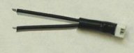
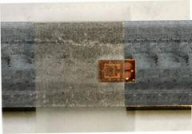
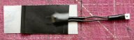
After
the epoxy cured, I took a 1 1/4 inch piece of vinyl electrical
tape and folded over one end to make a tab.
I laid the gauge on a piece of non-stick backing from a
self-adhesive label, and then pressed the tape onto the gauge.
Notice in the photo how the edge of the tape covers the
gauge, but not the solder tabs.
Also, this was a recycled connector as you can tell by
the heat-shrink tubing between the connector and the gauge.
I
put another piece of electrical tape over the gauge and the
leads, then trimmed it with scissors.
I wrote the gauge factor on the opposite side of the
backing and I am now ready to install it onto a rifle barrel.
Finger
Flick Test
I connected my strain gauge assembly to the device, ran the
program, and gently flicked the strain gauge with my finger.
To my surprise, it registered.
I flicked the gauge a couple of more times just to make
sure it was working correctly.
In the above graph you can see the results.
By the way, this flick test is recommended by the
device manufacturer for the gauges they sell.
Installing
Onto a Barrel
The device came with all the instructions for installing the
gauge onto a barrel. Based
on those instructions, I needed to decide if I wanted a
temporary or permanent installation.
For a temporary installation, I use Loctite 401
available from Small Parts, Inc. (www.smallparts.com).
The gauge can be removed using acetone.
For a more permanent installation, I use the Armstrong
A-12 epoxy also available from Small Parts, Inc.
I can also use J-B Weld to attach the gauge as long as
I don’t allow the epoxy to touch any exposed wiring.
As mentioned before, J-B Weld contains iron powder so
it is not electrically insulated.
At the time
I purchased the strain gauges, an engineer from Vishay
contacted me with a question regarding my application for the
gauges. I explained
how I wanted to measure pressure in the chamber of a rifle and
asked how best to attach the gauge.
He stated, “In
a pressure measurement on a cylinder, the gages that we quoted
(single-grid, uniaxial) would be applied perpendicular to the
length of the barrel, such that the gage is parallel to the
circumference of the barrel.”
This agreed with the installation instructions from the
device manufacturer.
My test
rifle was my Remington 700 BDL in 6mm Remington caliber.
I decided to permanently attach the gauge to the
underside of the barrel so it would be out of the way.
Using acetone, I degreased the portion of the barrel
onto which I planned to mount the gauge.
I removed the gauge from the non-stick backing being
careful to lift by the tab.
I applied a drop of A-12 epoxy to the strain gauge and
spread it in a thin layer with a toothpick.
I then pressed it firmly to the degreased portion of
the barrel pushing away from the solder tabs.
I routed the wires along the barrel and applied some
additional epoxy to keep them in place.
This prevents me from straining the wires during normal
handling and perhaps pulling them off the gauge.
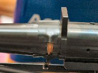
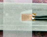
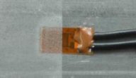
Notice
in the picture at the left the vinyl tape in front of the
recoil lug, under which is the strain gauge.
Also, notice the wires, the connector, and the epoxy
holding the wires against the barrel.
The small piece of electrical tape holds the wires
against the barrel until the epoxy cures.
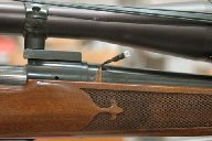
I routed a channel
inside the stock so it would not come in contact with the
wires. These wires
will stay out of the way just below the scope as seen in the
next photo.
Live
Fire Test
I took my rifle, the unit, my laptop, and some verification
reloads to the range. The
reloading manual I used stated the verification loads should
measure
62,500 PSI in a tight-chambered test barrel.
I would expect the loads to measure less than that in a
standard chamber, but using these loads helped me to judge how
close and accurate the strain gauge was.
I wasn’t really shooting for accuracy; I just wanted
to see how the strain gauge registered.
It is
always a good idea to have a verification load.
The adhesive used to attach the strain gauge to the
rifle barrel can weaken over time, which can cause a lower
reading. Therefore,
when testing new loads, I should always fire a verification
load first and compare it with an original verification load
to ensure I’m getting the same reading.
The above
graph shows the results from the live fire session.
The average pressure reading was 62,362 PSI; close
enough to the expected value.
I did have to add an adjustment factor to get the
correct readings. I’m
now ready to measure my reloads.
Mistakes
I Made
This project took me a few years to complete.
I started this project in December, 2004 and completed
it in April, 2008. I
made many mistakes along the way, but this is how we learn.
I’ve listed my painful learning mistakes below:
- The
solder tabs on the gauge are very delicate.
I ruined two gauges by having my soldering iron too
hot. I was
also so nervous I didn’t leave the soldering iron on the
leads long enough to get the solder to stick to the tabs.
Eventually I perfected the process.
- I
didn’t epoxy and heat-shrink the end of the connector
where the wires were soldered to the pins.
During my initial test, the wires broke off the
connector. Of
course, this happened at the range so I couldn’t test
anymore!
- I
got very erratic traces during my initial test.
It turned out the battery was weak in the device,
and of course, I didn’t have a spare battery with me!
Again, this happened at the range.
The device has a standby mode that uses a very
small amount of battery power.
After a short time, the battery goes dead.
I installed a switch in the unit to completely
disconnect the battery when I’m not using the unit. This
saves battery power. I
also bring a fresh 9V battery with me just in case.
- I
used J-B Weld epoxy the first time I sealed a connector
and the soldered leads on a gauge and got no readings when
I did the “finger flick” test.
J-B Weld has iron powder in it, which means it is
not electrically insulated.
It caused a short, so I got no readings.
Scratch another strain gauge assembly!
- I
attached the first strain gauge to my rifle using Loctite
401. Over
time, this affected the gauge so I didn’t get any
readings. I
destroyed the gauge removing it from the barrel.
I attached another gauge and decided to make it
permanent so I used epoxy instead.
- I
didn’t “flick” test my work, so when I went to the
range to test my first gauge and installation, I got no
readings. There’s
not much you can do at the range, so I packed up the
rifle; a wasted range session.
(Not really, I always bring other guns to shoot.
I was, however, disappointed that I didn’t get
any pressure readings from my rifle.)
- During
the initial “flick” tests, I had the sensitivity of
the unit set too low so it never registered.
I had to set the sensitivity high enough to
register. This
may also have been part of the problem why it didn’t
register at the range, but now if it’s sensitive enough
to register a flick, I can adjust the sensitivity to
register a live shot.
- I
installed the first two gauges in parallel with the
chamber, rather than perpendicular.
This caused erratic or no readings.
Of course, I destroyed the gauges when I removed
them from the barrel.
I installed the gage in parallel with the barrel
because the gauges initially sent with the device were
installed this way, and I thought I could install the new
gauges the same way.
Addendum
So now that I can measure chamber pressure, how do I use this
information? I
have a pet .45 LC hog load of 20 grains of 2400 under a 300
grain hard cast wide flat nose gas check bullet.
This load chronographs at 1527 feet per second (FPS)
from my 24-inch Marlin 1894 Cowboy.
Using a strain gauge, the pressure for this load
measured 32,454 PSI. Needless
to say, this is above SAAMI maximum for the .45 LC.
Please remember, this is my load for my gun, and must
be approached with caution.
At
a local gun show I purchased 8 pounds of Accurate Arms (AA) #9
powder. This
powder can be used for the same loads as Alliant 2400.
In fact, they are right next to each other on the burn
rate chart. But,
just how interchangeable are these two powders.
So, I put some loads with 20 grains of AA #9 through my
Marlin 1894 Cowboy to compare the measurements.
The
data for 20 grains of AA #9 showed that the pressure went up
an average of almost 2,000 PSI, but the velocity only went up
an average of 14 FPS. I
would probably drop this load about 2-3 tenths of a grain.
In fact, maybe it would be better to measure by volume
rather than weight to get equal performance.
However, without the strain gauge I would not be able
to make this comparison.
Parts
Sources (prices as of 4/1/2008 without taxes or shipping)
|