The Kitchen Table Gunsmith
  
   
Main menu  


Ruger® Single-Action Revolver Disassembly/Reassembly and Spring Replacement
by Roy Seifert

Click here to purchase a CD with this and all Kitchen Table Gunsmith Articles.

Disclaimer:  This article is for entertainment only and is not to be used in lieu of a qualified gunsmith.  Please defer all firearms work to a qualified gunsmith.  Any loads mentioned in this article are my loads for my guns and have been carefully worked up using established guidelines and special tools.  The author assumes no responsibility or liability for use of these loads, or use or misuse of this article.  Please note that I am not a professional gunsmith, just a shooting enthusiast and hobbyist, as well as a tinkerer.  This article explains work that I performed to my guns without the assistance of a qualified gunsmith.  Some procedures described in this article require special tools and cannot/should not be performed without them.

Warning:  Disassembling and tinkering with your firearm may void the warranty.  I claim no responsibility for use or misuse of this article.  Again, this article is for entertainment purposes only!

Tools and firearms are the trademark/service mark or registered trademark of their respective manufacturers.


1.  MAKE SURE YOUR REVOLVER IS UNLOADED!

2.  Open the loading gate.

3.  Press in the base pin latch with your right thumb and retract the cylinder base pin until it touches the ejector rod handle.

4.  Roll the cylinder out of the right side of the frame.

5.  Remove the grips by first removing the grip screw, then pulling each grip panel free of the frame.  Do not twist the panel or it may split.


6.  Point the muzzle straight up and cock the hammer.

7.  Insert a pin into the hole in the hammer strut that protrudes below the mainspring seat.  (I use a piece of broken drill bit.)

8.  Pull the trigger to release the hammer.

9.  Remove the two legs of the hammer return spring from the pin.


10. Using a proper size screwdriver bit remove the five screws that hold the grip frame to the cylinder frame. 


If this is a Bisley model you will need to obtain a 7/64” ball end allen wrench to remove the two allen screws.  Please note which screw goes into which position as all the screws are different.  (I lay the screws in a flat container in their approximate position looking at the gun upside down.)

11. Remove the grip frame by gently pulling it to the rear and down.

12. Remove the cylinder latch and pin from the grip frame.

13. Remove the pawl plunger and spring from the rear of the cylinder frame.

14.To replace the trigger return spring remove the trigger spring retaining pin with a punch.

15. Slide out the spring.

16. Slide in the new spring.

17. Replace the trigger spring retaining pin.


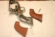
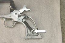
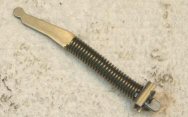
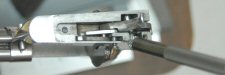
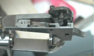
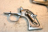
18. To replace the mainspring, first remove the hammer strut/mainspring assembly from the grip frame.  Note the orientation of the round end of the strut.  It should be pointing up.
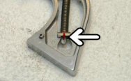
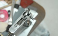
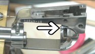
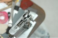
19.  Place the strut in a vise as shown.

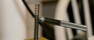
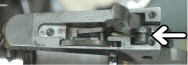
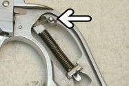
20. Use pliers to push down on the mainspring seat until you can remove the pin.

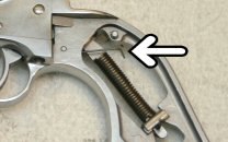
21. Gently relieve tension from the mainspring.

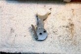
22. Remove the factory mainspring from the hammer strut.

23. Install the new mainspring on the hammer strut.

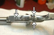
24. Insert your pin through the mainspring and hole in the hammer strut.

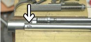
25. Turn the mainspring in so it compresses until the end of the spring is against the pin.

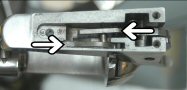
26. Hold the mainspring seat in a pair of pliers and set it against your retaining pin so the end of the hammer strut is through the notch.

27. While holding the seat with the pliers remove the pin.

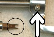
28. Push down on the seat until the hole in the strut is visible.

29. Reinsert the pin into the hole in the hammer strut thereby retaining the mainspring and mainspring seat.

30. Remove the assembly from the vise and reinstall in the grip frame.  Be sure the round end is pointing up.

31. Turn the cylinder frame and barrel upside down with the barrel to your left.

32. With a small punch depress the end of the loading gate detent spring and push out the trigger pivot pin from right to left looking at the gun upside down.  (The detent spring sets in the groove in the trigger pivot pin.  This holds the pin in the frame.)

33. Push out the hammer pivot pin from right to left looking at the gun upside down.

34. Pull up on the trigger just enough so you can unhook it from the transfer bar, then remove the trigger.

35. Remove the cylinder latch and loading gate detent spring.

36. Remove the hammer, pawl, and transfer bar all together.  Note how they are arranged.  If you plan to convert your pawl into a free-spin pawl, now is the time.

37. Remove the loading gate by pulling it out of the frame.

38. Remove the ejector housing screw.

No Photo

39. Remove the ejector housing, ejector rod and ejector spring.

No Photo

40. Remove the cylinder pin.

41. Remove the base pin latch nut from the base pin latch.  At this time you can replace the base pin latch spring with a stronger spring.

NOTE:  I made a two-prong base pin nut tool as shown in the circle in the photo.  I took the proper sized screwdriver bit and cut out the center with my high-speed rotary tool and a cutoff wheel.

If you shoot very light loads for cowboy competition, you should completely disassemble your gun every 500 rounds as described above so you can clean all the nooks and crannies in both the cylinder and frames.  If you shoot black powder you should always completely disassemble your revolver for a thorough cleaning.

Reassembly

During reassembly I suggest cleaning all screw threads with Acetone and using a drop of blue Loctite to hold them in place.  I was shooting a cowboy match one time and had the ejector rod housing, ejector rod, and ejector spring follow a shot downrange.  I never did find the screw, but I learned my lesson after that!

No Photo

1.      Insert the cylinder pin into the cylinder frame.

No Photo

2.      Insert the ejector rod and spring into the ejector housing.  The fat end of the ejector spring goes toward the frame.

3.      Insert the ejector rod housing into the frame and secure with the screw.  (Don’t forget the Loctite!)

4.      Turn the frame upside down on your table with the barrel to the left.

5.      Install the loading gate into the cylinder frame.

6.      Insert the cylinder latch and loading gate detent spring. 

a.      Be sure the cylinder latch sets in the slot cut in the frame, and the pivot pin sets inside the detent spring. 

b.      Make sure the end of the detent spring sets flush in the loading gate detent.

7.      Install the pawl onto the hammer.

8.      Slide the hammer, pawl and transfer bar into the hammer slot.  The pin on the transfer bar points in towards the hammer.

9.      Install the hammer pivot pin.  The groove should be away from you on the non-loading gate side.

10.  Lift up on the transfer bar just enough so you can connect the trigger to the pivot pin.

11.  Lower the trigger in place.

12.  Using a small punch depress the loading gate detent spring and insert the trigger pivot pin from left to right (looking at the gun upside down) with the groove in the pin facing you.  You may have to use a larger punch to align the holes in the cylinder latch and trigger with the trigger pivot pin.  Push the pin all the way into the frame until it locks in place (The curve in the loading gate detent spring falls into the groove in the pin.)

13.  Replace the pawl plunger and spring in the cylinder frame.

No Photo

14.  Install the hammer mainspring assembly in the grip frame (if removed).  Be sure the round end is pointing up.

15.  Push the two legs of the trigger return spring down so they are below the mainspring assembly.

16.  Install the cylinder latch plunger and spring into the grip frame

17.  Install the grip frame onto the cylinder frame.

a.      Make sure the end of the trigger return spring is on top of the trigger.

b.      Make sure the pawl plunger spring is flat against the grip frame and not pinched or bent.

c.      Make sure the end of the hammer strut is in the groove in the hammer.


18.  Using a drop of Loctite blue, install the grip frame screws as follows:

a.      The shortest screw goes into the bottom hole in front of the trigger guard.

b.      The next two screws that are the exact same size, or allen screws for a Bisley model, go into the holes at the top of the grip frame on either side of the hammer.

c.      You now have 2 screws left.  Both go into the holes on the bottom of the grip frame on either side of the rear of the trigger guard.  The shorter screw goes on the right (loading gate side).

d.      The longest screw goes into the hole on the bottom of the grip frame on the left (non-loading gate side) of the trigger guard.  This long screw sets in the groove in the hammer pivot pin and prevents it from sliding out.  Be sure you know which side the groove is on or you can damage the screw and hammer pivot pin.

19.  Hook the legs of the trigger return spring over the pin.

20.  Point the muzzle straight up and cock the hammer.

21.  Remove the pin from the hammer strut hole.

22.  Pull the trigger to release the hammer.

23.  Reinstall the grip panels and grip panel screw.  Use a drop of Loctite here, but don’t over tighten the screw or you can warp and/or split the grip panels.

No Photo

24.  Open the loading gate and reinstall the cylinder.

25.  Depress the cylinder base pin latch and slide the base pin into the cylinder until it locks in place.  You may have to rock/rotate the cylinder to get the pin in place.  Be sure the pin is all the way in and latched.


   © Copyright 2008 Roy Seifert.