Fine-Tuning a Rock Island Armory M1911A1
by Roy Seifert
Click here to purchase a
CD with this and all Kitchen Table Gunsmith Articles.
Disclaimer:
This article is for entertainment only and is not to
be used in lieu of a qualified gunsmith.
Please defer all firearms work to a qualified
gunsmith. Any loads
mentioned in this article are my loads for my guns and have
been carefully worked up using established guidelines and
special tools. The
author assumes no responsibility or liability for use of
these loads, or use or misuse of this article.
Please note that I am not a professional gunsmith,
just a shooting enthusiast and hobbyist, as well as a
tinkerer. This
article explains work that I performed to my guns without
the assistance of a qualified gunsmith.
Some procedures described in this article require
special tools and cannot/should not be performed without
them.
Warning:
Disassembling and tinkering with your firearm may
void the warranty. I
claim no responsibility for use or misuse of this article.
Again, this article is for entertainment purposes
only!
Tools
and firearms are the trademark/service mark or registered trademark
of their respective manufacturers.
Introduction
If you have been keeping up with my articles you know I
wanted to get into shooting SASS® Wild Bunch matches based
on the movie The Wild Bunch. These matches require
large-caliber, big-bore guns; a lever-action rifle – my
Marlin 1894 cowboy in .45 LC will work, a Winchester 97 or
model 12 pump-action shotgun – I just finished modifying a
Winchester 97 (refer to my article
Modifying a Winchester 97 for Competition), and a
1911 .45 automatic pistol. I have two modern 1911 .45’s in
my gun collection, but I wanted to shoot traditional which
meant I needed a standard, G.I. pattern 1911 .45.
I found a
phenomenal deal on
Gunbroker for a new-in-box Rock Island Armory M1911A1
.45 for $330! One other person bid on it and raised the
price from $330 to $345; but it was still an excellent
deal. With shipping and transfer costs the total came to
$392, but Armscor was having a $50 rebate program at the
time so total cost to me was $342. If you can purchase a
1911 .45 for under $600 nowadays you are doing well, but
under $400 is a steal!
This is
the second Armscor Rock Island Armory 1911A1 I’ve owned.
The first one I purchased I gave to my son as a Christmas
gift. It had a number of problems; most of which I was able
to repair.
-
The
feed ramp was milled off-center in the frame. I
couldn’t fix this but it didn’t seem to affect the
feeding reliability of the gun
-
The
trigger pull was 10 pounds. I replaced the sear and
disconnector to get a decent trigger pull.
-
The
chamber in the barrel was undersized and would not
chamber ammunition. I had to ream out the chamber to
proper specifications to get ammo to chamber reliably.
Refer to my article
Reaming a .45 ACP Chamber.
By the
way, my son reports that he has never had any failures with
that gun, and all of his friends want to shoot it because of
the excellent trigger. You just can’t beat a 1911 with an
excellent trigger!
Armscor
makes a fine, functional handgun built to G. I.
specifications. But because they are mass produced nothing
is hand fitted and many of the parts still have rough
tooling marks from the manufacturing process. The manual
that came with the gun stated that the gun would need
approximately 500 rounds to break it in. That’s a lot of
ammo! The process of breaking-in a firearm is really
nothing more than shooting it enough so the parts will be
polished and wear-in together. I can eliminate much of the
break-in requirement by polishing the necessary parts and
areas myself. This will improve both the function and
reliability of the gun, not to mention saves on ammo.
Initial
Assessment
After I picked up the gun from my dealer I did a cursory
examination and function check. Everything worked as it
should and the trigger pull was actually decent at 4 1/2
pounds. The thumb safety required a hydraulic press to
operate (ok, I’m exaggerating, but my thumb is still sore
from trying to engage the thumb safety) but I can polish and
re-contour the edge that rides along the plunger to make
this easier to function. This gun came with the narrow WWI
front sight so I will have to install taller, wider sights
which are legal for a traditional gun.
I took
the slide off of the frame and found most of the mating
surfaces had milling and tooling marks left over from the
manufacturing process. These will have to be polished out
to facilitate reliability and smooth functioning.
Everything on this pistol was Parkerized, which meant they
all had a rough finish which will also need to be polished.
I wonder if WWI and WWII era 1911’s came off the wartime
assembly line rough like this. Perhaps they had to in order
to meet wartime production needs. These guns were designed
to function in the dirt, dust, and mud of war and were loose
out of necessity. Accuracy was “minute-of-enemy soldier”,
not bull’s-eye.
So am I
trying to make a silk purse out of a sow’s ear? Not really;
I just want to make a mass-produced handgun function
reliability. It’s not a target or tactical pistol, but it
is a competition pistol so it has to function reliably. I
don’t have to get all shots to touch at 25-yards; I only
have to keep a group to “minute of steel” accuracy. I have
built three 1911 pistols from scratch so I will apply many
of the polishing and fitting techniques I learned from the
late Dave Sample to this gun.
Slide
Work
I decided to start with the slide since this will require
the least amount of work. I completely stripped the slide;
removing all internal parts. Just so I only have to say
this once, when I exposed bare metal after polishing, I
applied cold blue to protect the metal.
Polish
the Slide
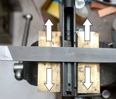
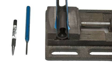
I placed
the slide upside down in my padded vise leaving about 1/4”
of it above the top of the jaws. I used a bastard file and
draw-filed the bottom of the slide rails to remove the
milling marks. Draw filing moves the file back and forth
90-degrees to the surface being smoothed as shown in the
above photo. This removes metal but doesn’t leave deep
filing marks. I was careful to keep the file flat so the
rails were nice and flat. I didn’t want to remove all of
the tooling marks since the slide was already loose on the
frame, just polish down the high areas. I finished
polishing with 400-grit wet/dry sand paper to complete the
process.

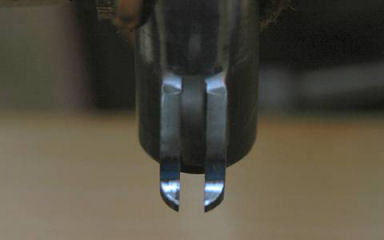
The small
rail where the disconnector and hammer ride had a lot of
tool marks so it too needed to be polished. I first used a
#0 Swiss pillar file I purchased from Brownells
#191-398-990 to smooth this area of the slide, being
sure to keep the file flat against the rail. I didn’t use a
lot of pressure on the file; I let the file do the work for
me. I completed the process with 400-grit paper to get this
surface smooth.

In order
to make it easier to feed a round from the magazine I
smoothed the breech face so that it shined and all of the
tool marks were removed. I used a 400-grit stone using very
light strokes, then finished with a 600-grit stone. Again,
I wanted the tools to do the work for me.
Working
the Barrel
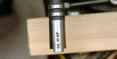
Based on
my previous experience with a RIA gun I first checked the
chamber to make sure it was up to spec. I dropped a couple
of different reloads into the barrel and they chambered just
fine. I also dropped a .45 ACP go headspace gauge into the
chamber to make sure it fit. This chamber seems to have
been reamed correctly at the factory.
I
polished underneath the barrel where it sits in the barrel
bed of the frame, and the top of the barrel and barrel
hood. I shoe shined this area using 400-grit paper to get
it nice and smooth. I didn’t remove the tooling marks, just
made these two areas smooth by knocking off the high spots.
I used a
400-grit stone and smoothed the back and sides of the lower
lugs where they hit against the frame when the barrel
unlocks and drops down out of battery. This just needed to
be smooth, not pretty.
I used a
Cratex tip to polish the front of the lower barrel lugs.
These lugs ride against the slide release pivot pin so they
needed to be smooth. I was careful not to allow the bit to
slip or touch any areas other than the front of the lower
lugs.
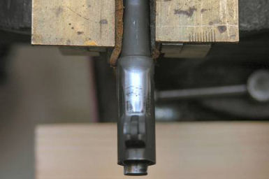
At the
top of the feed ramp in the barrel throat is another sharp
edge I needed to bevel so cartridges will feed reliably. I
took the safe edge of a file (the edge with no teeth) and
scraped this edge back and forth to make a very slight
bevel, just enough to break the sharp edge. Then I polished
the entire throat with a Cratex bit.
Working
Slide Parts
All of the internal parts of the slide have to fit and
function together properly for reliability. I worked each
part individually which consisted mostly of polishing.
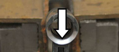
Checking
and Adjusting Extractor Tension
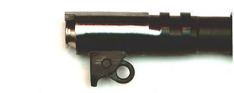
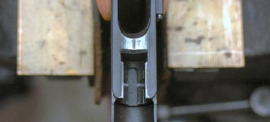
Tuning an
internal extractor is basically bending the extractor
(adjusting tension) until the extractor will hold a loaded
round. I completely installed all the parts in my slide and
inserted a loaded .45 ACP cartridge under the extractor hook
and against the breech face. On my pistol the cartridge
stayed in place as shown in the above photo indicating the
extractor tension was correct. If the cartridge did not
stay in place I would have had to adjust the extractor
tension.
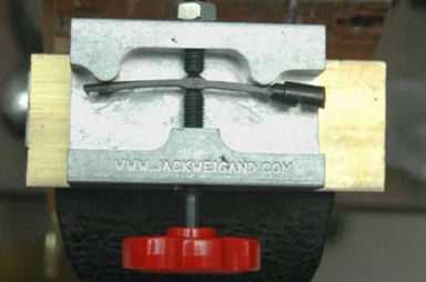
The
proper tool for adjusting extractor tension is the Weigand
Extractor Adjusting Tool available from MidwayUSA
#931460 or Brownells
#957-000-037. This tool bends the extractor to add the
proper amount of tension to hold a loaded round in place.
My extractor did not need any adjustment.
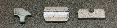
Fitting
the Firing Pin Stop
The
firing pin stop fit very tightly in the slide. This is a
good thing to prevent the firing pin stop from dropping out
of the pistol during recoil. However it required a punch to
remove and replace it in the slide. I laid the flat back of
the firing pin stop on a piece of 400-grit paper and
polished the rear until the Parkerizing came off. I tried
the firing pin stop in the slide and continued to polish
until I could insert and remove the stop with my fingers,
but it was still tight in the slide. I was careful not to
remove too much metal; it still needed to be tight.
Polishing
the Firing Pin
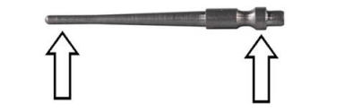
The
firing pin was binding inside the firing pin tunnel which
could cause misfires. I chucked the firing pin into a drill
and polished the front of the pin where it fits through the
firing pin hole, and the collar around the rear of the pin
where it rides in the tunnel. Now the firing pin moves
freely in the firing pin tunnel without binding.
Replacing
the Sights
As mentioned before this gun came with the narrow WWI front
sight. I wanted taller and wider sights for a better sight
picture. Rather than purchase new sights I fabricated my
own out of 1/8” flat steel bar stock. Although I have made
dovetail front sights before (refer to my article
Fabricating a Custom Front Sight) I wanted to
maintain the original staked-on front sight.
I found
some examples of taller front sights on the Internet that I
decided to copy. The front sight I chose to copy was 0.180”
tall as measured from the top of the slide. Jerry
Kuhnhausen states that the rear sight should be 0.035” –
0.045” higher than the front sight.
I chose the middle at 0.040”. Now for some basic math:
0.180” -
Front sight height above top of slide
0.180” +
0.040” = 0.220” - Height of rear sight above slide
0.09375”
– Depth of rear sight dovetail
0.220” +
0.09375” = 0.31375” – Total height of rear sight including
the base
0.125”
sight base – 0.050” depth of notch = 0.075” – Metal left in
sight base
0.31375”
Total height of rear sight – 0.075” = 0.23875” – Height of
rear sight blade
The rear
sight blade needed to be 0.23875” which I rounded up to
0.239”.
I milled
a 1/8” slot 0.050” deep in my 1/8” flat steel bar stock,
then cut out all of the parts. I used a small file to
remove any burrs and sharp edges. I squared the square
notch in the rear sight blade with a flat jeweler’s file;
the result was that the notch measured 1/8” (0.125”) which
is normal for target sights.

I tinned
the slot in the base and the bottom of the sight blade with
silver solder, then held both pieces in place with
vise-grips and heated them until the solder melted. I also
ran a bead of silver solder along the seam on both sides of
the blade so it would run into the joint. I allowed the
sight to air cool; cooling by using compressed air or water
can cause the silver-solder joint to become brittle and
weak. I took a flat jeweler’s file and removed any excess
solder from the base and blade.
I set the
blade in my machinist’s vise with the base up and used a
0.032” feeler gauge to level the base. The feeler gauge
ensured the base was not touching the top of the vise jaws.
I used a 65-degree sight base cutter I purchased from
Brownells
#080-621-495 and milled the dovetail angle on both sides
of the sight base. Because the cutter was made of high
speed steel I kept the speed of my mill to below 700 RPM per
Brownells instructions. I removed just enough metal so the
sight would just barely start in the dovetail. I used a
65-degree dovetail file I purchased from Brownells
#080-648-165 to finish removing metal so I could insert
the sight halfway into the dovetail with my fingers. I
finished tapping the sight in place with a brass punch. The
goal here is to make the sight easy to drift in the dovetail
slot to make windage adjustments, but tight enough so it
won’t move under recoil.
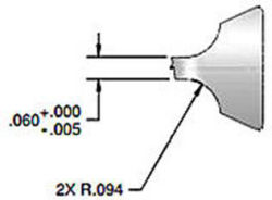
The
specifications for the rear sight call for a 0.094” radius
on the front and rear. 0.094” radius is 0.188” diameter
which is 3/16” or 0.1875”. With the rear sight in place I
put masking tape on the sides of the slide to prevent
marring the finish and leveled it in my machinist’s vise. I
used a 3/16” ball end bit to add the radius to the front and
rear of the sight and positioned it 0.005” above the top of
the slide. I milled each radius until I removed 0.032” from
each face of the sight blade. This allowed me to thin the
blade from 0.125” down to 0.060” as called for in the
specifications. I removed the rear sight, bead-blasted it
with glass bead media, cold-blued it, then reinstalled it
into the dovetail. It looks like it was factory produced.
Now for
the front sight. I removed the original front sight by
first using a pair of vice-grips and wiggling it back and
forth until it broke off of the stem. I was careful not to
mar the finish on the slide. I used a small punch to drive
the leftover stem out of the slide by punching it through
from outside to inside.
The
thickness of the new front sight measured 0.124”. The
narrow tenon needed to be 0.056” so I used my hobby CNC mill
to remove 0.034” from each side of the tenon. The new front
sight fit perfectly in the slot in the slide.

I
bead-blasted the sight using glass bead media, then
cold-blued the sight. You can see the result in the above
photo.
I applied
some green Loctite #609 to the tenon and inserted the sight
into the slot. I protected the sides of the slide with blue
painter’s tape and put the slide upside-down in a
machinist’s vise with the top of the sight touching the base
of the vise. I used a prick punch and steel 1/8” punch to
carefully peen and expand the end of the tenon until it
filled the bevel inside the slide. The bevel was deep
enough so I didn’t have to remove any excess peened metal so
the barrel bushing could rotate freely.
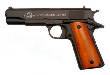
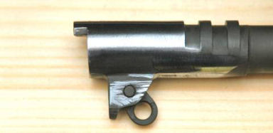
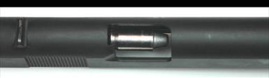
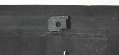
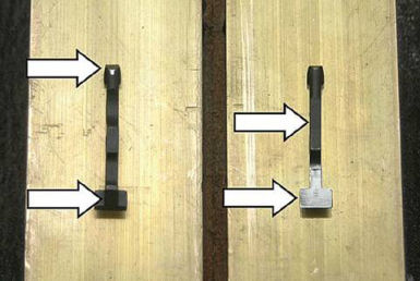
Here is
the gun with the new sights installed. If I did the math
correctly I should still be able to hit steel and be fairly
accurate. If not, I can always drift the rear sight, or
fabricate a new front sight.
Working
the Frame
The frame needed some polishing so parts would fit and
function together smoothly. Also since most of the parts
were rough Parkerized, they also needed to be polished to
work together smoothly.
Polishing
the Barrel Bed
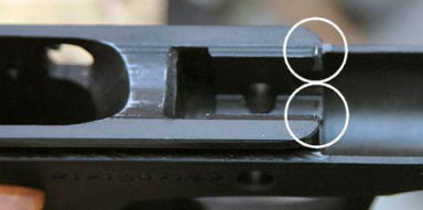
I wanted
to polish the barrel bed where the barrel sets against the
frame when it is out of battery. When I started to polish
the bed I found two raised burrs at the end of the barrel
bed. These appeared to have been raised by something
striking the end of the barrel bed; probably the recoil
spring guide rod. I took my #0 narrow pillar file and
carefully knocked off these burrs.
I wrapped
some 400-grit paper around the top of the barrel, turned the
barrel upside-down and polished the barrel bed in the
frame. Again, I left a lot of the tooling marks behind; I
just polished down the high spots.
Re-Contouring the Hammer Spur
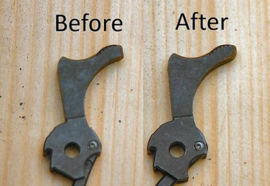
I am one
of those shooters that suffer from hammer bite. After
shooting only five rounds with my son’s pistol the web of my
hand was torn open. The hammer spur on the G.I. 1911 has a
thick, sharp edge at the bottom rear. I put a fine sanding
drum on my Dremel tool and thinned and rounded this edge. I
then polished with a Cratex bit and cold blued. Hopefully
this will eliminate the hammer bite.
Re-Contouring the Thumb Safety

As
mentioned before the thumb safety required an excessive
amount of force to engage and disengage. I used my Dremel
tool and a fine sanding drum to reduce the radius of the
front shelf of the thumb safety where it rides against the
plunger. I removed a little metal at a time and tried for
fit and function. When it functioned the way I wanted it to
I used a Cratex bit to polish that surface. Now I can
engage and disengage the thumb safety easily.
Adjusting
and Re-Contouring the Grip Safety
The grip safety was disengaging from the trigger almost at
the end of its travel. That meant I would have to grip the
gun tightly to disengage the grip safety. In the heat of
competition I may not always grip the gun the same way every
time so I wanted the grip safety to disengage earlier.
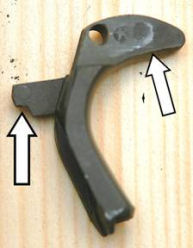
I filed
the bottom ledge under the front lobe of the safety until it
disengaged earlier in its travel. I took a few strokes with
a #0 narrow pillar file and tested the function frequently.
It still needed to function properly as a safety, but now it
disengages much earlier in its travel. I also beveled and
polished the sharp edges on the bottom-rear of the grip
safety. I didn’t want these edges to dig into my hand
during recoil.
Polishing
the Trigger Stirrup
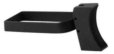
I used my
Dremel tool and a Cratex bit to polish the sides and rear of
the trigger bow. This removed the rough Parkerizing and
made these surfaces smooth. I cold blued all exposed
surfaces after polishing.
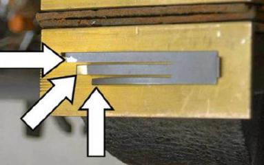
(viewed
from the front)
The sear
spring has three leaves that needed to be polished. I
polished the front of the left and center leaves, and the
rear of the right leaf. These surfaces ride against the
sear, disconnector, and grip safety so they needed to be
smooth.
I
polished the front and back of the bottom of the
disconnector by rubbing these areas on 400-grit paper set on
a flat surface. I used a Cratex bit to polish the tip of
the disconnector. The sear and sear spring ride against
these surfaces so they needed to be smooth.

I also
polished the rear and bottom of the sear. The trigger bow,
sear, disconnector, and sear spring all rub together so they
needed to be polished and smooth to facilitate a smooth
trigger pull.
Hammer
Follow
After polishing the parts of the fire control group I
performed a test for hammer follow. I locked the slide
back, and with no magazine in place, pressed down on the
slide release and allowed the slide to slam into battery.
The hammer dropped to the half-cock position every time,
which is called hammer follow. This is caused by one or
both of two conditions; either the sear spring was too weak,
and/or the hammer and sear mating surfaces were cut
incorrectly.
To test
if the hammer and sear mating surfaces were cut incorrectly
I again locked the slide in the open position and held the
trigger depressed when I released the slide. This time the
hammer stayed in the full cock position meaning the hammer
and sear mating surfaces were correct.
I
disassembled the gun and bent the center leaf of the sear
spring forward to add more tension. This increased the
trigger pull to 4 3/4-pounds – still acceptable for
competition – but eliminated the hammer follow problem.
Function
and Fire Tests
I loaded one round in a magazine, loaded the magazine into
the pistol, charged the round and fired the pistol. The
empty case was ejected and the slide locked back as it
should.
Next I
loaded two rounds in a magazine, charged the first round,
then fired the pistol. I was looking to see if the gun
would double-fire or go full auto. This gun did not. I
fired the second round and the slide locked back as it
should.
Finally I
fired a full magazine to see if the gun functioned properly,
and it did. I think it’s now ready for competition.
Wild
Bunch Match October 25, 2014
I attended my first Wild Bunch match sponsored by the
Walnut Grove Rangers in Ellenboro, NC. We fired 105
pistol rounds spread over six stages. My RIA 1911A1
functioned flawlessly! I did not have any failure-to-feed
or failure-to-eject malfunctions. I had one reload that did
not have enough powder in it so it short-cycled the gun
causing a jam which I had to clear on the clock, but this
was the ammo’s fault, not the fault of the gun. More
importantly, the front sight did not shoot loose or come
off. I was a bit worried since this was the first time I
installed a front sight by staking it in place. I still
suffered from hammer bite; the web of my right hand had a
bloody blister by the end of the day, so I guess this is
something I will have to live with.
As for
accuracy the new sights allowed me to place the shots right
where I needed them to go. When I did my part I was ringing
steel all day. Believe it or not, I had two stages where I
fired the pistol clean, but missed a rifle or shotgun
target. Well, as they say, there is no target big enough,
or close enough that you can’t miss. By the way, I fired
traditional which meant I fired the gun one-handed. I came
in third place in the traditional category out of four
shooters, and placed 6th overall out of 12 shooters. Not
bad for my first Wild Bunch match.
Summary
I could have purchased a G.I. slide, slide parts, and frame
parts to convert one of my modern 1911’s into a G.I pattern
pistol, but purchasing these parts would have cost almost as
much as this entire pistol! Plus my two modern pistols were
all hand fitted so another slide might not fit properly. I
built a 1911 .22 pistol (refer to my article
Building a Dedicated 1911 .22LR Pistol) so I could
have purchased the parts to convert it to a G.I. .45, but
again the total cost of the parts would have been almost as
much as this RIA pistol. If the price of the gun had been
much above $400 it would have been cheaper to purchase the
parts, but now I have a complete pistol without having to
swap out parts.
Many of
the specifications I used to fabricate parts came from Mr.
Rio Benson of Benson Consulting, LLP. He developed a
complete set of technical drawings for the M1911-A1 pistol.
You can download the complete set of drawings by clicking on
the link below.
M1911 A1 Drawings
|