Making a 1911
Trigger
by Roy Seifert
Click here to purchase a
CD with this and all Kitchen Table Gunsmith Articles.
Disclaimer:
This article is for entertainment only and is not to
be used in lieu of a qualified gunsmith.
Please defer all firearms work to a qualified
gunsmith. Any loads
mentioned in this article are my loads for my guns and have
been carefully worked up using established guidelines and
special tools. The
author assumes no responsibility or liability for use of
these loads, or use or misuse of this article.
Please note that I am not a professional gunsmith,
just a shooting enthusiast and hobbyist, as well as a
tinkerer. This
article explains work that I performed to my guns without
the assistance of a qualified gunsmith.
Some procedures described in this article require
special tools and cannot/should not be performed without
them.
Warning:
Disassembling and tinkering with your firearm may
void the warranty. I
claim no responsibility for use or misuse of this article.
Again, this article is for entertainment purposes
only!
Tools
and firearms are the trademark/service mark or registered trademark
of their respective manufacturers.
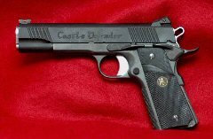
Awhile ago I built a 1911 .45
ACP from parts using an 80% frame.
I milled the slide rail slots in the frame, and
hand-fitted all parts to produce a fully- functioning,
reliable 1911 pistol. I
have used this gun successfully in a number of 3-gun matches,
and it is now my concealed carry gun.
Yes, I would trust my life with this gun.
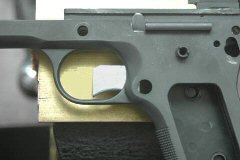
Unfortunately I’ve never
been very pleased with how the trigger fit in the frame.
It seemed like the trigger slot in the frame was cut
too large which allowed the trigger to wobble, both vertically
and horizontally. The
vertical movement would definitely affect trigger let off; if
I moved the trigger shoe up the pull was nice and crisp.
If I moved the trigger shoe down, the let off had some
creep. There’s
almost nothing worse than an inconsistent trigger to affect
accuracy. I was
discussing this with a gunsmith friend of mine who specializes
in 1911’s and he suggested that I make my own trigger.
 Removing
the Stirrup Removing
the Stirrup
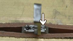
I took a spare trigger I had laying around the shop and
removed the stirrup from the trigger shoe.
The steel stirrup is staked in the aluminum shoe by two
stamped indentations as you can see in Figure 1.
I took my Dremel tool with a cut-off wheel and
carefully removed aluminum from around the stirrup on the side
away from the over travel screw 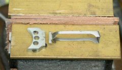 until
I could remove it from the trigger shoe. until
I could remove it from the trigger shoe.
Fabricating a New Trigger Shoe
I purchased a 3/8” x 1 1/2” x 12” piece of aluminum bar
stock from Online
Metals. The 1
1/2“ width allowed me to cut two trigger shoes side by side.
I measured the trigger shoe slot in the frame and using
my CAD program I designed a new trigger shoe that was .937”
high x .66” wide x .268” thick.
I made the height and thickness a couple of thousandths
larger than they needed to be so I could finish final fitting
by hand. I laid
out two shoes side by side as shown in Figure 3 so I could cut
them both out at the same time.
I set up my hobby CNC mill and using a 3/16“ flat end
mill I first milled the surface of a 1 1/2“ square section
down to .268”. Then,
using the same bit, I cut out the two trigger shoes.
Note that even though I used a CNC mill to cut out the
shoes, the same can be accomplished with a hacksaw and files,
but it will take a lot longer.
 Fitting
the Trigger Shoe to the Frame Fitting
the Trigger Shoe to the Frame
First I beveled the top and bottom edges to 45 degrees.
This allowed the shoe to fit in the cut in the frame
even if the corners of the slot are not exactly square.
Then I laid a sheet of 320 grit wet/dry paper on a flat
surface and began polishing the sides of the shoe until it
would fit in the slot. To
test the fit I inserted the shoe lengthwise in the slot to see
if it would fit in both the top and bottom as shown in Figure
4. I continued to
polish until it would fit.
The final thickness was .266”.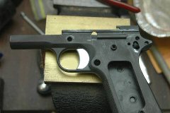
Next I again used the 320
grit paper and polished the top and bottom of the trigger shoe
until it would move freely in the cut-out in the frame.
The final height was .935”.
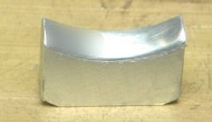 Radiusing
the Front of the Trigger Shoe Radiusing
the Front of the Trigger Shoe
At this point the trigger shoe fit in the frame perfectly; it
moved freely with no top to bottom or side to side wobble.
But the front was flat with a sharp edge, which I need
to remove. I put a
fine sanding drum in my Dremel tool and removed the sharp
front edges of the shoe on each side.
This put a gentle radius on the front of the trigger.
I finished polishing this surface with some 320 grit
wet/dry paper wrapped around a 3/8” wooden dowel chucked in
my drill. I ran
the drill at a medium speed and polished the front of the
trigger shoe until no more scratches from the sanding drum
could be seen.
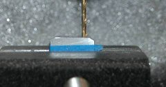 Drilling
the Over Travel Set Screw Hole and Cutting the Stirrup Slot Drilling
the Over Travel Set Screw Hole and Cutting the Stirrup Slot
Next I drilled the hole for the over travel set screw, and cut
the slot for the stirrup to set in.
First I wrapped the trigger shoe with some masking tape
to protect the surface, then squared and leveled it in a
machinist’s vise on my CNC mill.
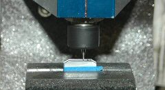
I used a #36 drill bit and drilled a hole .208” up
from the bottom of the trigger shoe.
This will eventually be tapped for a 6-32 set screw.
 The
slot for the stirrup should be .054” wide, and in the center
of the shoe. Ok,
now to oil the rusty brain cells.
The shoe is .266” wide; subtract the width of the
slot .054” leaves .212”.
Divide that by 2 gives you .106” on either side of
the slot. I’m
using a .04” wide end mill bit, so if I start at the edge of
the shoe, move the bit .106”, that will put the center of
the bit over the near edge of the slot.
I have to move the bit an additional .02” (half the
diameter of the bit) so the edge of the bit is cutting at
.106”. I cut
this slot until the depth reached .132”.
I move the bit another .014” and cut to a depth of
.132” so the final width of the slot was .054” (bit width
of .04” + .014” = .054”).
I removed the shoe from the vice, removed the tape,
cleaned up the edges, and tapped the over travel hole with a
6-32 tap. The
slot for the stirrup should be .054” wide, and in the center
of the shoe. Ok,
now to oil the rusty brain cells.
The shoe is .266” wide; subtract the width of the
slot .054” leaves .212”.
Divide that by 2 gives you .106” on either side of
the slot. I’m
using a .04” wide end mill bit, so if I start at the edge of
the shoe, move the bit .106”, that will put the center of
the bit over the near edge of the slot.
I have to move the bit an additional .02” (half the
diameter of the bit) so the edge of the bit is cutting at
.106”. I cut
this slot until the depth reached .132”.
I move the bit another .014” and cut to a depth of
.132” so the final width of the slot was .054” (bit width
of .04” + .014” = .054”).
I removed the shoe from the vice, removed the tape,
cleaned up the edges, and tapped the over travel hole with a
6-32 tap.
Setting
the Stirrup in the Shoe
When commercial manufacturers assemble the stirrup to the shoe
they use a jig. I
used the pistol frame as a jig.
First I used acetone to clean the slot in the trigger
shoe and that part of the stirrup that fits into the slot.
I put a drop of epoxy in the slot and carefully
inserted it into the frame from the front (through the trigger
guard). Then I
inserted the stirrup through the rear of the frame until it
was inserted into the slot.
I was very careful not to spill any epoxy or I might
not be able to remove the trigger.
I was also careful to make sure the stirrup was
installed correctly.
 After
the epoxy set up I removed the trigger from the rear of the
frame and set the shoe in my vise.
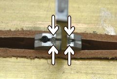
I used a prick punch to make indentations in the
aluminum on either side of the stirrup bar to stake the
stirrup in place. The
stirrup was now solidly in place and did not move. After
the epoxy set up I removed the trigger from the rear of the
frame and set the shoe in my vise.
I used a prick punch to make indentations in the
aluminum on either side of the stirrup bar to stake the
stirrup in place. The
stirrup was now solidly in place and did not move.
Finally I removed the
trigger, put a drop of Loctite blue in the over travel screw
threads and inserted a 6-32 x 1/2“ set screw.
I reassembled the frame and adjusted the set screw
until the hammer would fall without having the half-cock notch
touch the sear.
 I
once again disassembled the gun, lubricated the new trigger,
and reassembled the entire gun.
Now, my new trigger has very minimal wobble, and the
trigger pull is consistent.
Finally I’m pleased with my project. I
once again disassembled the gun, lubricated the new trigger,
and reassembled the entire gun.
Now, my new trigger has very minimal wobble, and the
trigger pull is consistent.
Finally I’m pleased with my project.
|