|
Reactivating
a Springfield
1903-A3 Drill Rifle
by Roy Seifert
Click here to purchase a
CD with this and all Kitchen Table Gunsmith Articles.
Disclaimer:
This article is for entertainment only and is not to
be used in lieu of a qualified gunsmith.
Please defer all firearms work to a qualified
gunsmith. Any loads
mentioned in this article are my loads for my guns and have
been carefully worked up using established guidelines and
special tools. The
author assumes no responsibility or liability for use of
these loads, or use or misuse of this article.
Please note that I am not a professional gunsmith,
just a shooting enthusiast and hobbyist, as well as a
tinkerer. This
article explains work that I performed to my guns without
the assistance of a qualified gunsmith.
Some procedures described in this article require
special tools and cannot/should not be performed without
them.
Warning:
Disassembling and tinkering with your firearm may
void the warranty. I
claim no responsibility for use or misuse of this article.
Again, this article is for entertainment purposes
only!
Tools
and firearms are the trademark/service mark or registered trademark
of their respective manufacturers.
Table
of Contents: Click
on a topic to move to that subject.
Introduction
 When
I was in high school I attended a military class run by the California
Cadet Corps which was under the California National Guard.
In fact, I was the commander of the unit my junior and
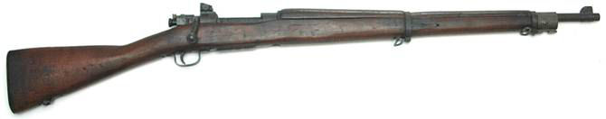
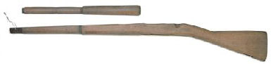
senior years. We
used deactivated Springfield
1903-A3 rifles for drill; the barrel was plugged, the bolt
face was welded, and the striker was ground down, but
everything else on the rifle was functional.
Most of us cadets wanted to own one of these rifles, so
ever since my high school days I’ve wanted to have a
functioning
Springfield
1903-A3. When
I was in high school I attended a military class run by the California
Cadet Corps which was under the California National Guard.
In fact, I was the commander of the unit my junior and
senior years. We
used deactivated Springfield
1903-A3 rifles for drill; the barrel was plugged, the bolt
face was welded, and the striker was ground down, but
everything else on the rifle was functional.
Most of us cadets wanted to own one of these rifles, so
ever since my high school days I’ve wanted to have a
functioning
Springfield
1903-A3.
A reader of
the Kitchen Table Gunsmith, Ray, recently contacted me asking
for permission to use my disclaimer on his web site.
I gave him permission, but wanted to know what he was
working on since I am always interested in a new gunsmithing
project. His
excellent article, with many very helpful photos, explained
how to convert a deactivated Springfield
1903-A3 drill rifle into a shooter titled 03-A3
Drill Rifle Facts and Recovery Process.
He had apparently purchased a batch lot of these
deactivated drill rifles from the Civilian
Marksmanship Program (CMP) and was selling parts and
complete rifles. I
purchased a complete rifle from him for the mere price of $220
including shipping to my FFL dealer.
A few minutes of paperwork plus $15 transfer fee put
this piece of American military history in my hands.
Prior to
adoption of the
Springfield
in 1903 the official rifle of the U.S. Military was the .30-40
Krag-Jorgensen. This
rifle had many shortcomings that were exposed during the 1898
Spanish-American war, especially when compared to the 1898
Mauser. Development
of a new rifle began in 1900 with the final design being
adopted in 1903 based on the Mauser action.
Eventually the
United States
had to pay royalties to Mauser Werke in
Germany
since the action was very similar, but when WWI hostilities
broke out the
United States
stopped paying royalties.
Production of the 1903-A3 variant began in 1941 and
ended in 1944, however the rifle continued to be used in both
Korea
and Vietnam.
I’ve
always been fascinated with
U.S.
military rifles. I
currently have an AR15, M1A, M1 Carbine, and M1 Garand in my
collection; all are functioning shooters.
A
Springfield
1903-A3 was a rifle missing from my 20th century
U.S.
military rifle collection.
After I picked up my rifle from my FFL dealer I did a
little research on the Internet and found M1903.com;
a web site dedicated to 20th century
U.S.
military firearms. It
turns out my rifle was built by Remington in August, 1943
which coincides with the date stamp of 7/43 on the ruined
barrel. An
interesting side note; my newer model M1 Garand has an older
Springfield Armory receiver built in 1942, but my older model
’03-A3 has a newer Remington receiver built in 1943!
Initial
Assessment
I completely disassembled the rifle for
inspection and to determine what work I needed to perform, and
what parts I needed to replace.
This is what I found:
- No
front sight blade –The rifles we had in high school had
the front sight blade installed, but I remember numerous
cadets, including myself, getting cut by them during drill
exercises so that is probably why this rifle didn’t have
one.
- It
looked like the magazine cutoff had been welded, but
someone had worked on it to make it function again.
- Rear
sight base peened and bent – probably from cadets
dropping the rifle multiple times, but I was still able to
adjust the sight for windage and elevation.
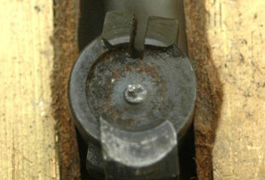
- Firing
pin hole welded on the bolt face
- Striker
(firing pin) was cut off so just the collar was left.
- Chamber
was torched and a steel rod welded in place
- Barrel
was tack welded to the receiver
- Missing
ejector and ejector pin
- Safety
would not rotate
- Upper
band was loose
- Upper
band screw was stripped
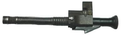
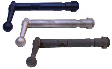
Broken
Safety Plunger
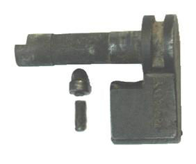
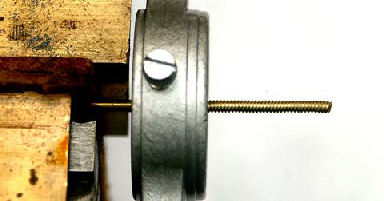
To my
surprise I couldn’t rotate the safety, which made
disassembling the bolt a bit challenging.
I discovered the shaft was broken off of the safety
plunger. This
shaft guides the plunger into the hole, but now that it was
broken, the plunger was hitting the side of the plunger hole
effectively blocking it so it couldn’t move down.
I used a small screwdriver to align the plunger with
the hole and pushed down so I could rotate and remove the
safety. I’m
guessing since the plunger is longer than the space between
the shaft and the lever it was installed prior to installing
the shaft. I’ll
have to purchase a new safety assembly.
Removing
the Handguard Ring
The handguard ring would not come off because of
the tack weld on the bottom of the barrel.
I took a safe-edge #0 narrow pillar file #191-400-760
I purchased from Brownells and filed down the top of the weld
until it was even with the rest of the receiver so I could
slip the ring off of the barrel.
This turned out to be a stainless steel weld and would
not take parkerizing, but this was not a problem since the
weld was on the underside of the receiver and would be covered
by the stock.
Removing
the Welded Magazine Cutoff
Removing the welded magazine cutoff was much easier
than anticipated. Since
it was functioning all I had to do was remove the magazine
cutoff screw and spindle and remove the magazine cutoff from
the receiver. Although
the magazine cutoff functioned correctly, because this part
was so damaged from the welding I purchased a new one.
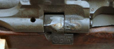
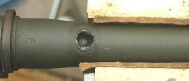
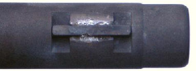
Milling
Magazine Cutoff Detents
Probably the ugliest part of this rifle was the
cratered receiver where the magazine cutoff was welded.
I could have had this TIG welded and then reshaped it,
but I decided to leave it and just re-parkerize it.
Leaving it as is I can brag about how I recovered a
drill rifle and show where it was originally welded.
However, I wanted the magazine cutoff to function
correctly so I cleaned up the detents.
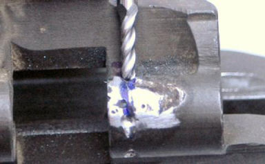
I took a
3/32” ball end milling bit and my high-speed rotary tool set
to the lowest speed and opened up the welded center detent.
I took a cone-shaped grinding bit and ground in the
beveled approaches on both sides of the new detent.
I then took a cone-shaped rubber polishing bit and
again used my high-speed rotary tool to polish out the
grinding marks on the beveled approaches.
I reinstalled the old magazine cutoff and tested it
with the bolt and everything worked as it should.
The center detent was in the proper position so the
bolt could be removed and installed easily.
I also cleaned up the ON and OFF detents with the
3/32” ball end bit because they had some metal splash from
the welding. Now
the magazine cutoff plunger sets securely into each of the
three detents.
Ok, so what
does the magazine cutoff do?
In the down or OFF position it will not allow the bolt
to come back far enough to feed rounds from the internal
magazine essentially making it a single-shot rifle.
In the center position it allows the bolt to be removed
and installed. In
the up or ON position it allows the bolt to come back far
enough so the rifle will feed rounds from the internal
magazine. Also
when in the ON position, after the last empty case is
extracted and ejected the follower prevents the bolt from
closing thereby indicating that the magazine is empty.
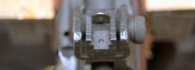
Cleaning
up Rear Sight Base
I
completely disassembled the rear sight and noticed that the
sight base was heavily staked onto the receiver.
I found on the Internet that this seems to be common
with rifles manufactured by Remington so I decided just to
leave it alone and treat it as part of the receiver.
I took a steel punch and pounded the sides of the rear
sight base until they were straight.
I took a file and cleaned up the burrs on the top of
each side, then used a rubber polishing tip and my high speed
rotary tool to polish out the file marks.
When I re-parkerize the receiver this will look great!
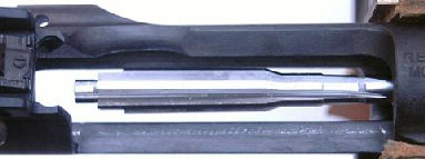
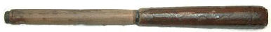
Removing
the Barrel
The most difficult part of the recovery process was
removing the welded barrel.
Ray used a lathe to not only remove the barrel weld,
but to remove enough of the barrel shoulder to reduce the
interference fit of the barrel to receiver face so he could
remove the barrel with a pipe wrench.
I don’t have a lathe so to remove the weld I used the
same safe-edge #0 narrow pillar file I used previously.
I started
at the end of the weld and rested the safe edge of the file
against the receiver face.
I began filing the weld being careful not to cut into
the receiver face. After
I filed off some of the weld to expose the barrel I rotated
the rifle so I could file off more of the weld.
I always made sure the safe edge of the file was
resting against some exposed receiver face to keep the file
square and flat.
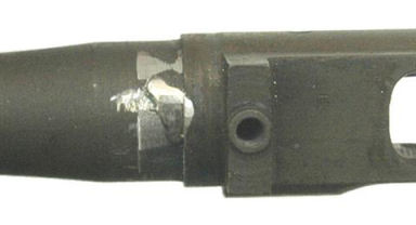
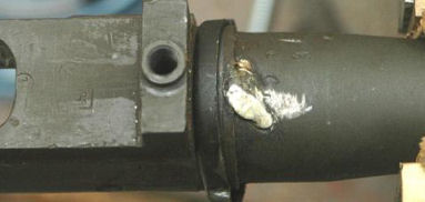
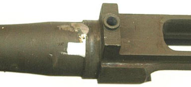
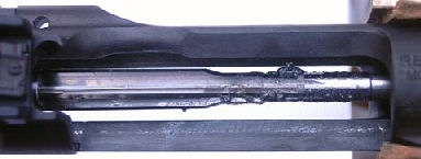
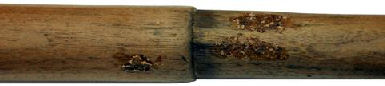
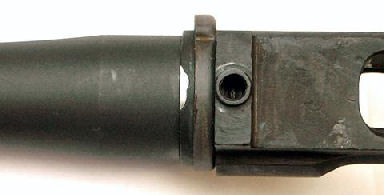
Because the
weld was so high I started filing on the other end of the weld
being careful as before. You
can see in the above photo that the weld started to form a
point at the top where both filed sides met.
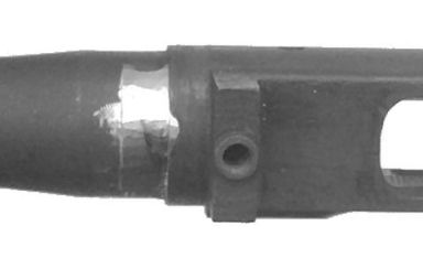
I continued
to file both sides of the weld until I had a bare-metal cut in
place of the weld indicating that I had removed the weld metal
and had started to cut into the barrel.
I filed a little deeper to make sure I had removed the
entire weld.
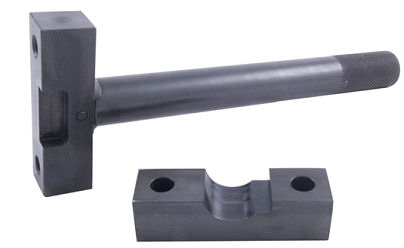
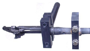
Because I
didn’t go completely around the barrel shoulder I still
needed to use an action wrench and barrel vise to remove the
barrel. I already
had the action wrench from Brownells so all I needed was the
Springfield
1903 Head #080-801-003.
A properly fitting head is important because this
prevents the receiver from warping or otherwise becoming
damaged when removing the barrel.
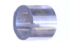
I also
already had the barrel vise, but I didn’t have a bushing
that fit the barrel, so I had to make one.
I marked the barrel just in front of the chamber swell,
and made another mark 1 1/8” farther down the barrel.
The barrel diameter measured at the two marks was
0.980” and 0.942” respectively meaning the barrel had a
0.968o taper. If
you are interested in how I calculated the amount of taper,
the math is at the end of this article.
I used BobCAD-CAM v20
to create the
CAM
code, then used my MAXNC
10 CL hobby CNC mill to mill the bushing from 1 1/8”
aluminum stock.
No matter
how hard I tried I couldn’t remove the front sight base from
the barrel, so I cut off the barrel about one-inch behind the
front sight base. This
is a throw-away barrel anyway and I ordered a replacement
front sight base.
I attached
the receiver wrench to the front of the receiver using the
Springfield
1903 head. I
coated the inside and outside of the barrel bushing with rosin
I purchased from Brownells #083-016-100,
positioned it on the barrel, then installed and tightened the
barrel vise onto the bushing.
I positioned the barrel vice in a well-supported bench
vise and used a 2-foot length of pipe on the action wrench to
gain some additional leverage.
Thanks to this additional leverage the barrel easily
came loose, even after almost 70 years.
As my father taught me; it helps to have the right
tools!
Replacement
Parts
I purchased the following parts from Gun
Parts Corporation (Numrich).
All the replacement parts came stamped with an “R”
indicating they were all manufactured by Remington; a perfect
match for my rifle.
- 1087210
new barrel
- 514340B
safety lock assembly
- 514510 striker
- 515370 magazine
cutoff
- 524910 front
sight base
- 524650 front
sight key
- 524900 front
sight blade
- 514520 bolt body
- 515760 ejector
- 515750 ejector
pin
Re-Parkerizing
I not only wanted my rifle to function like new, I
also wanted it to look like new so I decided to re-parkerize
the visible parts. Parkerizing
is a very simple, inexpensive process that applies a more
durable finish than bluing.
This is why manufacturers starting parkerizing military
guns to keep up with the demands of two world wars.
Parkerizing also covers up nicks, scratches, and other
imperfections, and this rifle has almost 70 years of
imperfections and cadet mishandling!
I have parkerized a number of guns and each one came
out beautifully.
I purchased
a jumbo combination (black & grey) parkerizing kit from Home
Parkerizingkits.com. I
used the grey to match the original military parkerizing on
early ’03-A3’s. Later
rifles came with a grey/green parkerizing.
I took all
the parts I wanted to re-parkerize and first removed any
unsightly burrs. The
new bolt body I received was blued and packed in cosmolene so
I first had to remove all the grease.
I bead-blasted the parts down to bare metal which gave
them a nice, even matte finish.
I thoroughly cleaned and degreased all the parts, and
prepared the grey parkerizing solution according to the
instructions. I
used nylon cable ties to suspend the parts and provide a means
to remove the part from the hot parkerizing solution.
I heated the solution in a large stainless-steel
cooking pot to 190oF and immersed the parts.
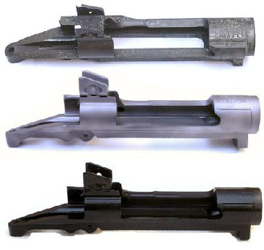
After the
parts stopped bubbling I removed them from the pot, thoroughly
rinsed them with hot water, then coated them with the provided
light oil. The
above photos show (from top to bottom) the original part, bead
blasted, and parkerized. As you can see from the
photos they came out very nice.
Some areas
on the receiver and the bolt sleeve wouldn’t take the
parkerizing. I
bead-blasted them again and then dipped them in an acid bath
made of 1 part muriatic acid and 4 parts tap water for about
30-seconds, then
thoroughly rinsed them in tap water.
This time the parkerizing came out evenly.
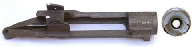
Polishing
and Mating the Bolt Locking Lugs
After I parkerized the parts I polished the bolt locking
lugs on the new bolt. This
ensured that the bolt locking lugs mated evenly with equal
pressure which can provide some increase in accuracy.
This process can also change headspace which is why I
performed it before I installed the new barrel.
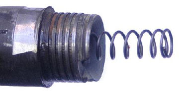
I installed
a spring onto the steel rod that was welded into the chamber
of the old barrel. I
screwed the old barrel onto the receiver so the spring applied
tension on the closed bolt.
I removed the bolt, applied some 800-grit lapping
compound onto the recoil lugs, then closed the bolt.
I opened and closed the bolt about 45-degrees to lap
the recoil lugs. The
spring applied rearward pressure on the bolt to facilitate the
lapping process.

After 10-20
open/close cycles I removed the bolt, cleaned the locking lugs
with brake parts cleaner and examined the progress.
I applied more lapping compound and continued the
open/close lapping process until both lugs were evenly lapped.
I removed the old barrel and cleaned both the receiver
and bolt with brake parts cleaner.
Installing
the New Barrel
The barrel I ordered from Numrich had a few
problems. First of
all there was no alignment mark on the side of the barrel as
found on military barrels.
So the only way I was able to index the barrel properly
was to install the front sight base and “eyeball” it.
I
discovered the slot in the barrel for the sight base key was
too wide. The
front sight base would not fit tightly onto the barrel because
the wide slot allowed the sight base to rotate.
I peened the edges of the slot until the key fit
tightly, then I silver-soldered the key in place.
Now the front sight base fits tightly onto the barrel
and does not rotate.
I screwed
the new barrel onto the receiver until it was hand-tight and
discovered that the barrel was rotated about 75o
which would make it way too tight.
The proper method for reducing the interference fit is
to turn down the barrel shoulder on a lathe, however as
mentioned before I do not have a lathe.
Another method for reducing the interference fit is to
use 400-grit lapping compound and lap the barrel shoulder to
the receiver. This
technique comes from Accurizing
the Factory Rifle by M. L. McPherson.
This method removes metal from both the receiver face
and barrel shoulder, but it also squares these two surfaces.
Because I am removing metal from the receiver face I
may not be able to put another barrel on this receiver.
Not a problem because I don’t plan to ever put
another barrel on this rifle.
I screwed
the new barrel onto the receiver until the barrel shoulder was
about 1/8” away from the receiver.
I took a toothpick and put some 400-grit lapping
compound into that space, then screwed the receiver down hand
tight. I needed to
be careful that I didn’t get any lapping compound onto the
barrel threads. I
set the barrel straight up in a vise and alternately loosened
and tightened the receiver.
After about 50 or 60 cycles of loosening and tightening
I cleaned off the lapping compound with brake parts cleaner
and checked my progress. A
grey ring was starting to form around the barrel shoulder and
receiver face.
I continued
this process until the barrel was about 16-degress off to the
right. This will
provide the correct amount of interference fit (tightness) for
the barrel and receiver. Also
there was a solid grey ring around the barrel shoulder and
receiver face indicating that the barrel was lapped and square
to the receiver.
I coated
the barrel bushing with rosin as before and slid it onto the
barrel. I
installed the barrel vise onto the bushing, and installed the
action wrench onto the receiver.
I put the barrel vise into the well-supported bench
vise and tightened the receiver until the front sight base was
vertical and centered.
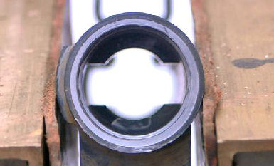
Reaming
the Chamber
The new barrel came with a chamber that was cut
0.005” short so I had to finish reaming the chamber to the
proper headspace. First
I measured the headspace of the new barrel.
A very important procedure when replacing a barrel is
to check the headspace. I
used the new bolt body so just the bolt face came in contact
with the gauge. When
testing headspace there should be no extractor or ejector
tension on the gauge.
I inserted
a .30-06 Go headspace gauge into the chamber and gently tried
to close the bolt body using just light finger pressure.
I never try to force a bolt closed on a gauge; light
finger pressure is all that is needed.
I used the Go gauge because this was a new barrel with
a short chamber. The
above photo shows that the bolt would not close all the way.
This is the point where I just started to feel some
friction. Because
the bolt would not close on the Go gauge indicated that the
chamber was too short.
I rented a
.30-06 chamber reamer from Elk
Ridge Reamer Rentals.
When it arrived I pushed the pull-through rod through
the chamber and out the bore until the reamer was visible in
the receiver. I
liberally lubricated it with cutting oil then pulled the rod
until I felt the reamer contact the chamber.
I gave it about 10 turns clockwise as viewed from the
muzzle; never
counterclockwise as this could break the cutting teeth.
I could feel the reamer cutting into the new barrel as
it cut a longer chamber and new throat.
I pushed
the reamer back into the action.
As shown in the above photo the flutes had steel dust
from the reaming process.
I removed the reamer and rod by pulling them back
through the action. I
thoroughly flushed the reamer and chamber with brake parts
cleaner to remove all chips and cutting oil, then ran a clean
dry patch through the bore from the chamber to the muzzle.
I used the Go headspace gauge to measure headspace as
described before. The
bolt still would not close on the Go gauge indicating I had to
do more cutting.
I repeated
the cut 10 turns, clean and measure process until the bolt
would completely close with the Go gauge in place.
The chamber and throat were now cut to the proper
length. I also
measured headspace with a .30-06 Field gauge just to make sure
the chamber was within specification and the bolt would not
close.
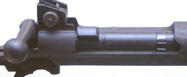
Reassembly
After I finished reaming the chamber I completely
reassembled the rifle with the replacement parts.
Everything went together as it should, and the re-parkerized
parts made the rifle look almost factory new.
Also the front sight base key didn’t have a notch so
I drilled a notch so the pin would fit.
I made sure all moving parts were either oiled or
greased before assembly.
Since all
the parts were now re-parkerized, which is a rough finish, the
bolt didn’t slide as easily and smoothly as it did before.
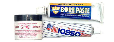
I purchased a tube of IOSSO bore cleaner from Brownells
#073-000-002
which has a very fine grit.
I put some on a Q-tip and spread it along the receiver
where the bolt travels. I
opened and closed the bolt about 20 times while placing
downward pressure on the bolt.
I cleaned off the excess cleaner from the bolt lugs and
receiver. Both the
bolt and receiver had streaks where the Parkerizing was
polished off. Working
the bolt while watching TV also helps to polish those newly-parkerized
surfaces!
Tightening
Upper Band
The upper band was very loose and it looked like
someone tried to tighten it by over-tightening the upper band
screw causing it to strip.
The upper band hole in the stock was too large causing
a large amount of slop and play in the upper band.
This may have been done on purpose to prevent cadets
from installing a bayonet.
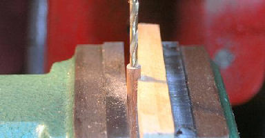
First I
drilled out the hole in the stock to 1/4”.
Then I took a piece of 1/4” hardwood dowel, cut it to
1 1/4”, and drilled a hole through the center using a #29
drill bit.
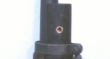
I glued the
hollow dowel into the stock, then cut and filed the ends flush
with the stock. I
reamed the hole with a #26 bit until the upper band screw
would fit and meet the threaded hole when installed with the
upper band. Now
the upper band has no slop or movement.
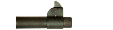
Polishing
Extractor Face
I discovered that the extractor wouldn’t slip
over the rim of a single-fed cartridge; however it worked
perfectly when feeding rounds from the magazine.
I put a rubber polishing tip on my high-speed rotary
tool and polished the face of the extractor.
Originally it had a sharp edge transitioning to the
bevel. I polished
that edge and the bevel, then cold-blued the entire extractor.
Now the extractor slips easily over a single-fed
cartridge.

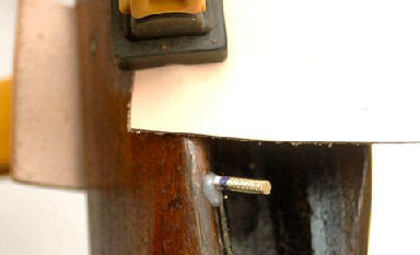
In the
above photo you can see a light area on the lower left of the
extractor face (indicated by the arrow) where the extractor
rubbed against the case head when single feeding.
This is the beginning of the transition line from the
extractor face to the bevel and was the area I polished.
This edge has to be smooth enough so when the extractor
meets the cartridge head it cams over the rim of the
cartridge.
Barrel
Break In
I performed this barrel break-in procedure with my
new M1 Garand barrel and it worked very well. It
is a combination of hand and fire lapping to polish the
chamber throat and lap the bore.
The purpose of this procedure is to polish out any
burrs left in the barrel throat from the reamer, and to polish
and gradually taper the barrel for increased accuracy and ease
of cleaning. Burrs
in the chamber throat can literally tear copper from a bullet
and cause excessive copper fouling in the bore.
Traditional
fire-lapping drives bullets impregnated with lapping compound
through the bore at very low velocities.
Cases used for fire-lapping have to be thrown away
because the brass case neck gets contaminated with the lapping
media. Although
this method does wonders for the bore, it also lengthens the
barrel throat which can reduce barrel life.
My method polishes the throat without increasing its
length, laps the bore and I don’t have to throw away the
cases!
First I
loaded 15 rounds of .30-06 with 5.0 grains of Red Dot behind a
150 grain FMJ boat tail .308 bullet and a large rifle magnum
primer. I use
magnum primers because there is so little powder in the case,
and anything less than 5.0 grains of powder will cause the
bullet to get stuck in the bore.
I put a
bore guide in the action to prevent the lap from depositing
compound in the chamber. I
wrapped a .45 cleaning patch around a 25-caliber bore brush,
and then impregnated the patch with USP
Bore Paste™ that I purchased from Midway
USA #
257358. I ran
the tight-fitting patch back and forth through the entire
length of the bore 20 times being careful not to allow the lap
to come all the way out of the muzzle, or all the way into the
chamber. This
performed the hand lapping part of the process and left a
small amount of compound in the bore.
I fired one low-velocity round through the barrel which
performed the fire-lapping.
I inserted the bore guide into the action, then again
using USP Bore Paste™ ran an impregnated tightly fitting
patch back and forth through the bore 20 times.
This cleaned any powder residue and fouling from the
bore and prepared it for a second low-velocity lapping shot.
After performing the lap/shoot process for 5 shots, I
thoroughly cleaned the barrel using solvent and dry patches. This
removed any residual lapping compound in preparation for the
next finer compound.

The photo
above shows a recovered lapping bullet.
You can see the dark areas caused by lapping the lands
and grooves in the bore.
Now I
impregnated a clean patch with J-B® Bore Bright #083-065-100
that I purchased from Brownells which has a finer grit and
performed the hand lap/fire lap sequence another five times as
before, then thoroughly cleaned the bore again with solvent
and patches.
Finally, I
performed the same hand lap/fire lap process another five
times using the ISSO bore cleaner which has the finest grit.
This process performed the final polish of the chamber
throat and bore. The
bore was mirror bright and smooth and was now ready for full
pressure loads, and the new throat was polished which will
prevent excessive fouling.
Lapping
the Muzzle
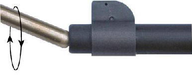
The last
thing I did just to make sure I hadn’t picked up any nicks
or burrs on the muzzle crown was to lap the muzzle.
This removes those nicks and burrs and makes the ends
of the lands and grooves sharp and even which also enhances
accuracy. I put
some 400-grit lapping compound on the end of a brass muzzle
lap I purchased from Brownells #080-764-350
attached to a variable speed drill.
With the drill running at about 500-700 RPM I touched
the ball end of the lap to the muzzle at the angle shown in
the above photo and rotated the drill through 360-degrees
keeping the lap at the same angle.
I did this for about 1 minute making sure I kept
rotating my drill in a circular motion.

I cleaned
the excess lapping compound off the muzzle and ran a cleaning
patch through the bore from breach to muzzle.
As you can see in the above photo, the muzzle had a
bright ring around the inside and the lands and grooves were
nice and sharp.
Taller
Front Sight
The ’03-A3 is designed to hit 5-inches high at
200 yards using M2 ball ammo, but I wanted to be dead on at
100 yards with a dead-center hold.
I did some quick ballistic calculations and found that
I would have to drop the shot 4.7-inches to be on at
100-yards. Since I
couldn’t lower the rear sight any more, I would need to have
a taller front sight. I
used my Front
Sight Height Calculator to determine that I would need to
raise the front sight 0.037-inches.
The standard front sight blade is 0.537” so the new
front sight blade would need to be 0.574”.
I scanned
the front sight blade into my PC, used CorelDRAW®
to trace around the image, then increased the height to
0.574”. I
exported the pattern to BobCAD-CAM
so I could create the tool code for my CNC mill.
I first rotated the pattern 90-degrees so the base was
vertical. This
would fit better in the one-inch wide 3/64” tool steel stock
I purchased from OnlineMetals.com
that I used to fabricate the new front sight blade.

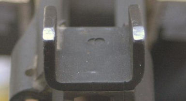
Once the
new blade was completed I used a jeweler’s file to remove
any burrs. I
installed the blade in the front sight base and used a #52
drill bit to mark the location of the mounting hole, then used
a center-punch to make the mark deeper.
You can clearly see the mark in the above photo.
I used my mill/drill and the #52 drill bit to drill the
mounting hole.
After the
hole was drilled I bead-blasted and cold blued the blade.
I installed it in the front sight base using a 1/16”
roll pin because I didn’t have a solid pin to mount the
blade. The pin was
nice and tight so the blade didn’t move.
Refinishing
Stock
I decided to refinish the original stock and
hand guard rather than purchase new ones.
I’ve refinished a number of gun stocks and they come
out looking almost like new, although this one is pretty beat
up.
I
completely disassembled the rifle and removed all the metal
parts from the stock and hand guard.
I used Klean-Strip®
KS-3 Premium Stripper that I purchased from my local home
improvement store to remove the old finish.
This stripper is a semi-paste that adheres to the wood.
I applied the stripper with a brush, allowed it to set
for 15 minutes according to the instructions, then wiped it
off with a paper towel. As
you can see from the above photo, the first application
removed almost all of the old finish.
I applied a second coat of stripper and used a stiff
nylon brush to work it into all the crevices.
I again wiped it off after 15 minutes.
After the third application I soaked a green scrubbing
pad in mineral spirits and rubbed down the wood to remove all
excess stripper and completely clean the wood.
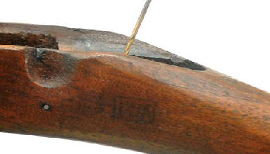
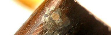
After the wood was stripped and cleaned it appeared
like someone tried to refinish this stock once before and did
a poor job of sanding. However,
many of the original cartouches became visible after I
stripped off the old finish.
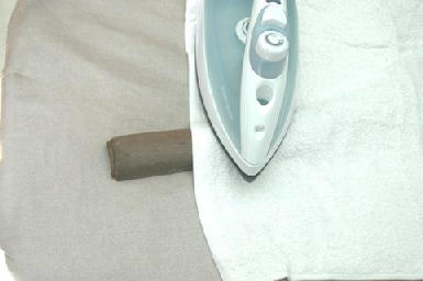
After the
wood dried I applied a wet cloth to the wood and pressed a hot
iron to the wet cloth. This
process steamed out any dents from the wood.
If this was a collectable stock I would not apply steam to the
cartouches since they are stamped (pressed) into the wood, not
cut. I steamed the entire surface of both the stock and hand
guard three times to make sure I raised as many dents as I
could, then set them aside to dry.
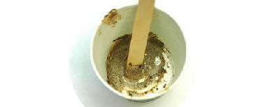
I took an
old stock I had in the shop and drilled a few holes in the
butt to get some walnut shavings.
I put the shavings in a mortar and pestle to grind them
into a powder. I
mixed the powder with some wood glue to make a paste and used
the paste to fill some of the gouges in the wood.
After the glue dried I sanded the filled spots, then
sanded the entire piece with a 220-grit sanding pad.
I used a pad so it would conform to the shape of the
wood.
I applied
my favorite stain, Minwax®
Gunstock #231, then wiped off the excess with a clean
cloth. I allowed
the wood to dry overnight.
After the
stain had been drying for about 8 hours I applied a coat of Minwax®
Clear Satin Fast-Drying Polyurethane to all the inside
areas of the stock and hand guard.
This will prevent moisture from getting into the stock
which can lie against the metal receiver or barrel and cause
rusting and pitting. I
have seen this condition in other military surplus rifles.
Once the
stain was dry I applied three coats of Birchwood
Casey® Tru-Oil®. Tru-Oil®
provides a durable, easy to repair finish that I use on all my
gunstocks. I
allowed each coat to dry for 6 hours.
After each coat was dry I burnished the surface with a
nylon stocking. I
don’t usually use steel wool because it can leave steel
filaments behind in the wood.
Repairing
Cracked Stock

The stock
was cracked from the magazine cutoff detent back to the wrist;
but it was only cracked on one side.
I couldn’t open the crack far enough to put in any
glue so I decided just to use pins.
I took a
1/16” brass rod and threaded it with a 4-32 die.
I threaded enough so I could cut two pins.
I used a
#44 drill bit and drilled a pilot hole in the stock.
I made sure I didn’t go through the bottom of the
stock.
I applied a
clamp to the stock to keep the crack as tightly closed as
possible. I cut a
piece of the threaded rod long enough so I could insert it
into the chuck of my variable speed drill.
I applied some epoxy to the threads of the pin and used
the variable speed drill at a very low speed to screw the pin
into the hole.
I carefully
trimmed the pin flush with the wood.
I touched up the wood with sandpaper, stain, and finish
to match the rest of the gun. After the glue dried on the
first pin I performed the same process to a second hole
drilled from the bottom of the stock.
Hopefully the crack will not spread any more.
Result
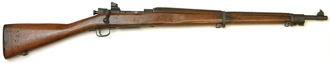
The above
photo shows the result of all my work.
The stock was in pretty bad shape to begin with, but it
now has a very nice finish, and as everyone keeps telling me,
it has character. All
the external metal has been refinished and everything
functions as it should.
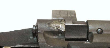
You can
still see a small spot of stainless steel where the old barrel
was tack-welded to the receiver.
As mentioned before, this is covered by the stock so
will not show.
I left the
receiver weld alone where the original magazine cutoff was
welded. Because of
the different consistency and hardening the weld metal
parkerized differently than the rest of the receiver.
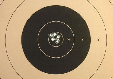
Ok, so how
does it shoot? Well
first of all, it kicked like a bolt-action .30-06!
I can shoot my M1 Garand all day with no problems, but
I needed to wear a recoil pad when shooting the ’03-A3.
This is why after so many years since high school I
never owned one! However,
with a brand new, lapped barrel and proper bench rest
technique, you can see the 100-yard result with the above
target. I am very
pleased with the result, and proud to own a piece of
U.S.
military history that I restored to shooting condition.
Final
Cost
$220
Rifle plus shipping
$
15 FFL
transfer
$264
New parts
$
55 Chamber
reamer rental
$
64 Parkerizing
kit
$
63 Action
wrench head
$681
Total cost
I already
had most of the tools and supplies mentioned in this article
which kept my costs low, so the prices shown above are what I
actually spent out-of-pocket.
Summary
So why go through all the trouble and expense
of converting this drill rifle into a shooter when I probably
could have purchased a shooter for about the same price from a
gun show? First of
all was the challenge of the project and doing the work.
Part of the pleasure was doing the work myself and
seeing the result.
Second of
all, my rifle now has a brand new barrel and refinished parts.
Even if you could find a new, never been fired ‘03-A3
it would cost upwards of $1,500+ whereas I spent $681 for
parts and tools including the price of the rifle.
A gun show rifle wouldn’t have a new barrel or new
finish.
Best of all
I now have a functioning
Springfield
1903-A3 for my collection that will last for thousands of
rounds. I know I
probably won’t come close to putting a thousand rounds
through this rifle, but I do enjoy seeing those longing looks
from fellow shooters when I take it to the range.
So the next time I participate in a bolt-action
military rifle side match, guess which rifle I’ll be taking
along!
I also want
to express my thanks to Ray Brandes for his excellent web site
and article on how to recover an ’03-A3 drill rifle.
His article and photos pointed me in the right
direction, and I was able to purchase an excellent example of
one of these deactivated drill rifles from him.
************************************************************
Calculating
Barrel Taper
Gunsmithing requires some math capability; especially when it
comes to measurement and dimensions.
I needed to calculate barrel taper so I could make a
tightly fitting aluminum bushing for my barrel vise.
My bushing
had to be 1 1/8” long to fit in the barrel vise so I made
two marks on the barrel just below the chamber swell that were
1 1/8” apart. The
barrel diameter at the two marks was 0.980” and 0.942”.
I made a drawing as shown above.
I moved
both vertical lines up until the bottom of the small vertical
line was at the end of the horizontal line.
This helped me to visualize what I needed to do.
So now I needed to know the length of the small
vertical section on the left.
I found this as follows:
0.980”
– 0.942” = 0.038”: difference
between large and small vertical lines
0.038” /
2 = 0.019”: 1/2
the difference because the small line is in the center of the
large line
So the
small line was 0.019”. I
drew a line from the bottom of the large vertical line to the
bottom of the small vertical line so now I had a right
triangle and I could use basic high school geometry to
calculate the angle. (High
school geometry; I can hear you readers groaning from here!)
First I
needed to find the length of the hypotenuse.
I’m sure we all remember Pythagoras’ theorem for a
right triangle; A2 + B2 = C2
where A and B are the sides of a right triangle, and C is the
hypotenuse. So now
I had:
0.019”
2 +1.125” 2 = C2 so solving for
C I got
C
= √ (0.019”
2 + 1.125” 2) or
1.1251604330050004029069759316584”
So now I
needed to find the angle indicated by the arc in the above
diagram. The angle
is represented by the Greek symbol theta ( ).
In high school geometry we learned SOH CAH TOA to
remember the relationships of the angles and sides of a right
triangle. They
stand for: ).
In high school geometry we learned SOH CAH TOA to
remember the relationships of the angles and sides of a right
triangle. They
stand for:
SOH:
Sine = opposite over hypotenuse
CAH:
Cosine = adjacent over hypotenuse
TOA:
Tangent = opposite over adjacent
The side
opposite from angle()
is 1.125” so I used the Sine function to find the angle.
I used the following formula:
Sine()
= 1.125” / 1.1251604330050004029069759316584” so solving
for
I got
= arcsine(1.125” / 1.1251604330050004029069759316584”).
On the scientific calculator that comes on your PC
arcsine is the INV check box.
So the angle worked out to be 89.032o.
This was very close to 90o which I knew was
right, but would have been much too large to make my bushing.
The two non-right angles of a right triangle equal 90o
so I subtracted 89.032o from 90o which
gave me 0.968o.
This was the angle I used to make the bushing.
My high
school math teachers would be so proud!
|